
Rigging field guide
Practical Rigging & Lift Planning
A field-focused guide to planning the pick, selecting and inspecting the rigging system, controlling the load and landing it without improvising around unknown weight, center of gravity or capacity.
Field guide: https://millwrightsupply.com/rigging-lift-planning-guide.html
Plan before touching the load
Build the lift around known information
A lift plan connects the load, lifting equipment, rigging configuration, people, route and landing point. The plan must be specific enough that the crew is not solving weight, capacity, clearance or communication problems while the load is suspended.
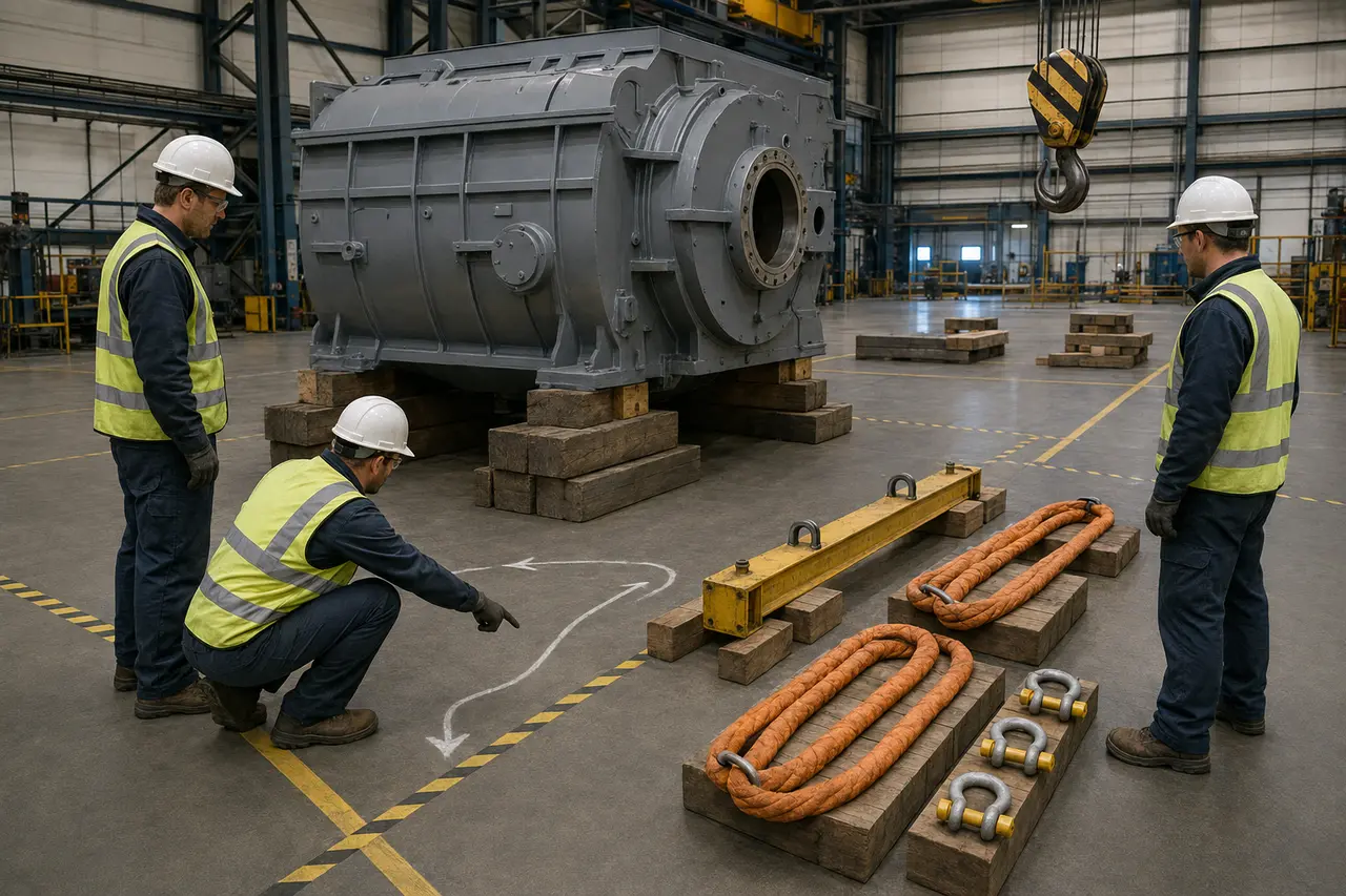
Every connection and destination must be known
- Define the loadConfirm the actual item, verified weight, dimensions, center of gravity, attachment points, condition and anything that can shift, drain or detach.
- Define the movementIdentify the starting support, lift height, travel path, orientation changes, obstructions, floor or ground limits and final landing arrangement.
- Choose the lifting methodSelect the crane, hoist, gantry, jack or other approved system whose rated capacity and operating range suit the complete move.
- Engineer special conditionsEscalate unknown weight, questionable lifting points, unusual centers of gravity, multiple lifting devices, personnel exposure or custom lifting accessories.
- Assign qualified rolesConfirm who directs the lift, operates equipment, rigs the load, signals, controls tag lines and has authority to stop the operation.
- Hold a pre-lift briefingWalk down the plan with the crew, including the first movement, stop signal, exclusion area, communication method and response to a changing condition.
If the weight, center of gravity, lifting point, capacity or communication method is uncertain, the lift is not ready. Stop and resolve the uncertainty before loading the rigging.
One connected system
Select every component for the actual configuration
Capacity is not the number printed on one sling. It is the capacity of the complete configured system after hitch, angle, load shape, attachment, environment and support conditions are considered under the approved plan.
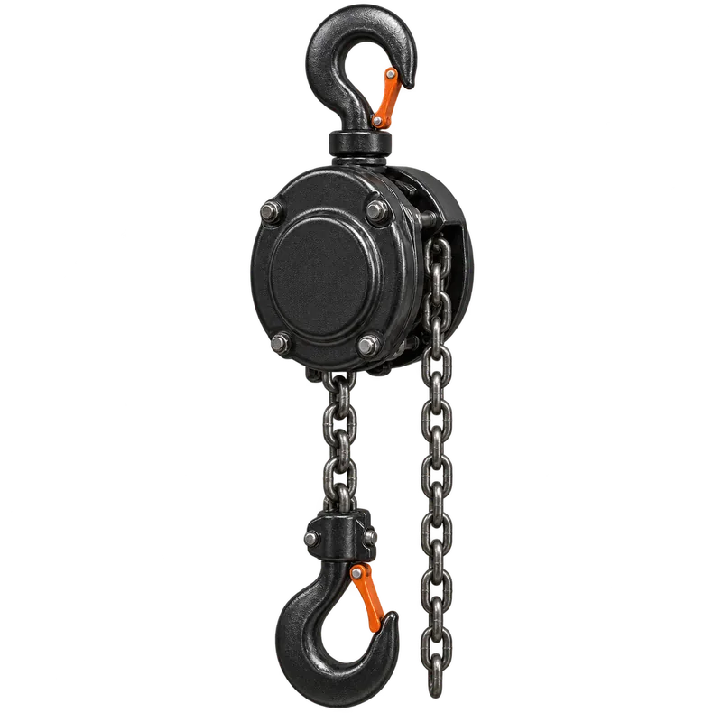
Hoists and lifting devices
Confirm rated load, lift, headroom, suspension, brake condition, controls and supporting structure. The support must be approved for the imposed load.
Explore manual hoists
Synthetic web slings
Useful where surface protection and flexibility matter. Protect against sharp edges and remove damaged or unidentified slings from service.
Explore web slings
Roundslings
Check the identification, cover, core condition, fittings and edge protection. A damaged cover can expose a load-bearing core that cannot be judged casually.
Explore roundslings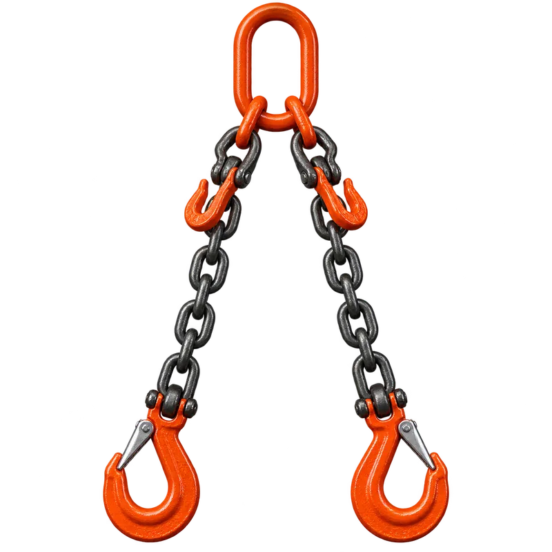
Alloy chain slings
Verify grade, tag, reach, fittings and manufacturer limits. Inspect links and attachments for wear, stretch, deformation, heat damage and unauthorized repair.
Review sling selection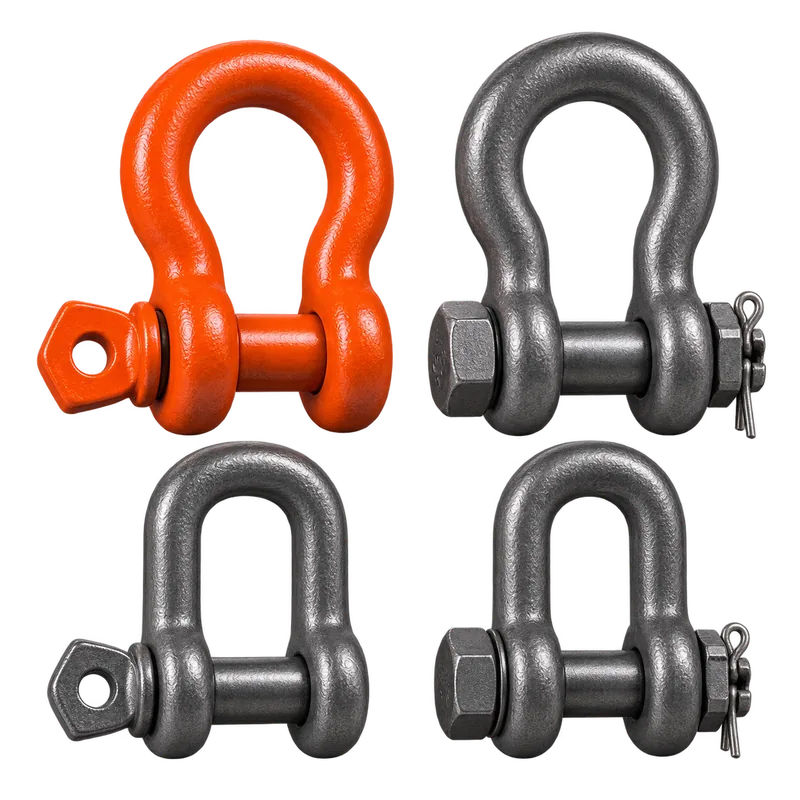
Shackles and hardware
Use the correct body, pin and loading direction. Confirm markings, fit, pin engagement, side-loading restrictions and compatibility with the connected components.
Explore shackles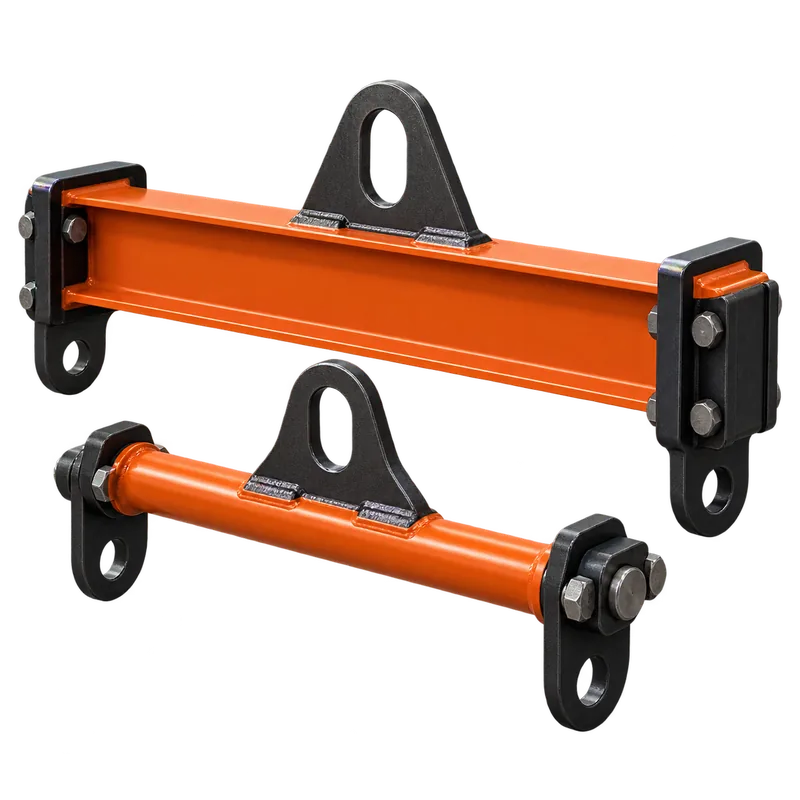
Beams and spreaders
Use only identified, rated and approved lifting devices. Confirm orientation, pick points, rigging geometry and any proof-test or engineering requirements.
Review rigging selectionGeometry changes force
Control center of gravity, sling angle and stability
Center of gravity
- Place the hook over the planned lifting point
- Arrange the rigging so the load cannot roll or tip unexpectedly
- Use a controlled trial lift to confirm balance
Sling angles
- Lower sling angles increase leg tension
- Use the manufacturer table or approved calculation
- Do not estimate capacity from appearance
Load attachment
- Use verified lifting points and correct hardware
- Protect slings from edges and damaging surfaces
- Secure loose parts and prevent internal movement
Support and structure
- Confirm beams, clamps, trolleys and anchor points are approved
- Check load path through every support
- Do not assume building steel is a lifting point
Tag lines and control
- Use them only where the plan calls for them
- Keep hands and body away from pinch and crush zones
- Never wrap a tag line around the body
Trial movement
- Take strain slowly and pause just clear of support
- Check balance, rigging seating and brake response
- Land the load if any condition is not as planned
Before each shift and during use
Inspect identification, condition and configuration
OSHA requires rigging equipment for material handling to be inspected before use on each shift and as necessary during use, with defective equipment removed from service. Manufacturer criteria and the applicable employer inspection program control the decision.
| Equipment | Pre-use focus | Stop / remove from service |
|---|---|---|
| Synthetic web sling | Legible identification, webbing, stitching, eyes, fittings and edge protection | Cuts, tears, broken stitching, burns, chemical damage, knots, exposed warning yarn or doubtful strength |
| Roundsling | Tag, cover, core feel, fittings and protection at contact points | Visible core, cut or heat-damaged cover, knots, abnormal lumps, damaged fittings or missing identification |
| Chain sling | Tag, link shape and wear, free articulation, hooks, master links and repairs | Stretch, bent or cracked links, gouges, heat damage, weld spatter, binding links or unauthorized repair |
| Wire-rope sling | Identification, rope body, lay, end terminations, fittings and lubrication condition | Kinking, crushing, bird-caging, corrosion, broken wires beyond criteria, heat damage or distorted fittings |
| Shackles and hardware | Markings, body, pin, threads, fit and intended load direction | Cracks, deformation, excessive wear, damaged threads, mismatched components or illegible rating |
| Hoist or puller | Nameplate, hook, latch, chain/rope, controls, brake, suspension and travel path | Unusual operation, slipping brake, damaged load chain/rope, distorted hook, missing rating or unsuitable support |
One plan, one direction
Control communication and the work area
Designated direction
Identify the person who directs the movement and the qualified signal person where required. Everyone must understand the stop signal.
Clear fall zone
Plan positions so people remain clear of suspended loads, pinch points, load travel and the path a component would take if the rigging shifted.
Stop on change
Loss of communication, unexpected movement, changing weather, obstructed view, interference or a questionable sound is a reason to stop and reassess.
From pre-lift to landing
A disciplined field sequence
Plan and inspect
Verify the load, route, capacities, components, roles and exclusion area.
Take strain and trial
Lift only enough to confirm balance, seating, clearance and control.
Move and land
Maintain communication, avoid shock loading and land on prepared support.
- Walk down the complete moveVerify the load, route, headroom, support, destination, personnel positions and equipment access.
- Inspect and stage the systemCheck every component, protect it from damage and keep unused rigging outside the work area.
- Connect without forcingSeat hooks, pins, slings and fittings correctly; do not hammer mismatched hardware or side-load components not intended for it.
- Take strain and trial liftRaise only enough to confirm balance, seating, clearance and control before committing to travel.
- Move deliberatelyMaintain communication and line-of-fire control; avoid shock loading, sudden direction changes and contact with structures.
- Land on prepared supportUse the planned cribbing, blocking or foundation arrangement so hands and feet never become temporary supports.
- Release and inspectConfirm the load is stable before slackening, then inspect equipment after unusual loading or any event that could have caused damage.
- Close the liftStore equipment correctly, quarantine defects and document the lift or inspection records required by the employer.
Primary references
Standards and manufacturer guidance
This guide is an orientation, not a lift plan or qualification. Applicable law, the employer's program, engineered lift documents and manufacturer instructions control.
Millwright tool questions
Frequently asked questions
Practical answers for comparing tools, planning the work and choosing equipment for the actual assignment.
What information belongs in a millwright lift plan?
A lift plan identifies the verified load and center of gravity, lifting points, rigging arrangement, capacities and angles, equipment and support conditions, travel path, landing area, roles, communication, hazards and stop criteria. The required level of engineering and approval depends on the lift and site rules.
Who is responsible for directing an industrial lift?
Roles must be assigned by the employer and site under the applicable procedure. The designated lift director, qualified rigger, signal person, equipment operator and crew each have defined responsibilities; anyone who sees an unsafe condition should communicate and stop work as authorized.
When should tag lines be used on machinery lifts?
Use tag lines only when the lift plan identifies that they improve load control without creating entanglement, pinch, electrical or line-of-fire exposure. Their material, attachment and handling position must suit the load, environment and procedure.
What rigging must be inspected before a lift?
Inspect every hoist, sling, shackle, hook, clamp, beam device, attachment and control component required by the plan, including identification and condition. Remove equipment with damage, missing markings or uncertain status from service and follow the manufacturer and site inspection criteria.
Continue into the directory
Compare the rigging equipment groups
Use the Rigging Equipment directory for sling, hoist, shackle, clamp and machinery-moving categories.