
Measure. Verify. Document.
Precision measuring tools
A practical guide to the indicators, levels, micrometers, calipers and gauges used to verify machinery condition—and the field habits that make their readings dependable.
Field guide: https://millwrightsupply.com/precision-measuring-tools-guide.html
Start with the required answer
A good instrument is only one part of a reliable measurement
Before choosing a tool, define what must be measured, the tolerance that controls the work and the reference the reading will be taken from. The instrument, setup, technique and record all have to support that requirement.
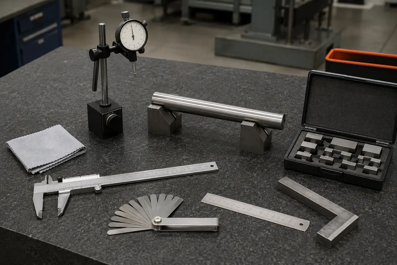
Contact through the true diameter
Define the check
Identify whether the job requires movement, size, level, clearance, flatness, squareness or another specific condition—and find the approved tolerance.
Build the setup
Select a suitable reference and enough range, accuracy and access. Keep stands, contacts and measuring surfaces clean, stable and correctly oriented.
Prove the reading
Check zero, repeat the measurement and use a reversal, reference standard or second method when the procedure or importance of the result requires it.
Never let the display decide the method. A tool can show a precise-looking number while the setup, contact angle, temperature or reference makes that number wrong.
What each group tells you
Ten core precision-measuring tool groups
These groups cover the measurements most often encountered in machinery installation, alignment, inspection and overhaul work. Choose the exact range and accuracy from the job requirement—not from a generic toolbox list.
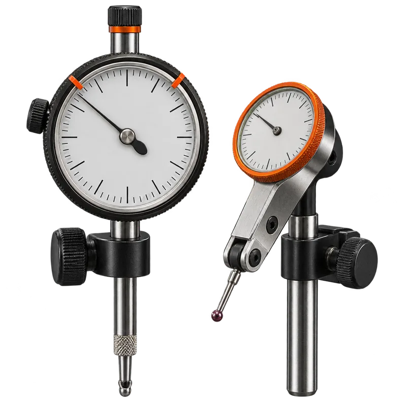
Dial indicators
Magnify small linear movement for runout, endplay, lift, flatness and relative-position checks. Travel, graduation, contact geometry and mounting style must fit the setup.
Explore dial indicators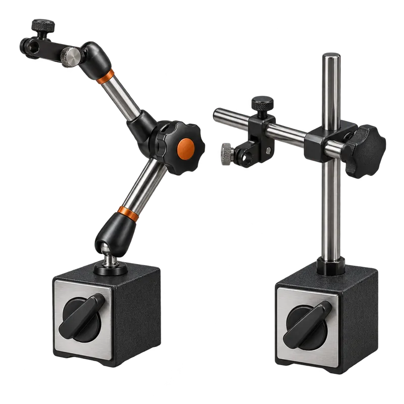
Magnetic bases and brackets
Hold an indicator relative to the chosen reference. Base contact, arm length, joint rigidity and fine adjustment directly affect repeatability.
Explore indicator bases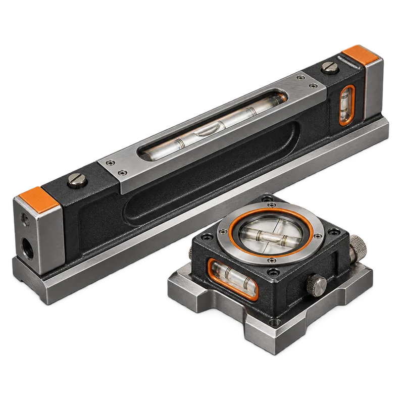
Machinist levels
Detect small elevation changes across bases, soleplates and precision surfaces. Sensitivity, length, temperature and reversal technique matter.
Explore machinist levels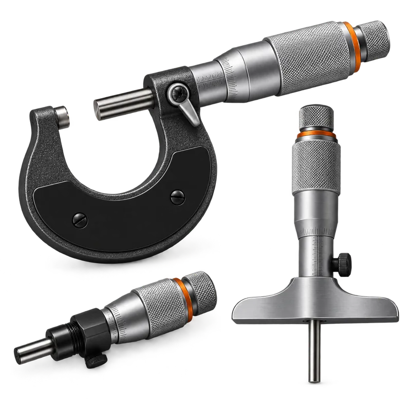
Micrometers
Measure shafts, journals, sleeves, shims and wear surfaces more closely than a general caliper. Clean faces and consistent measuring force are essential.
Explore micrometers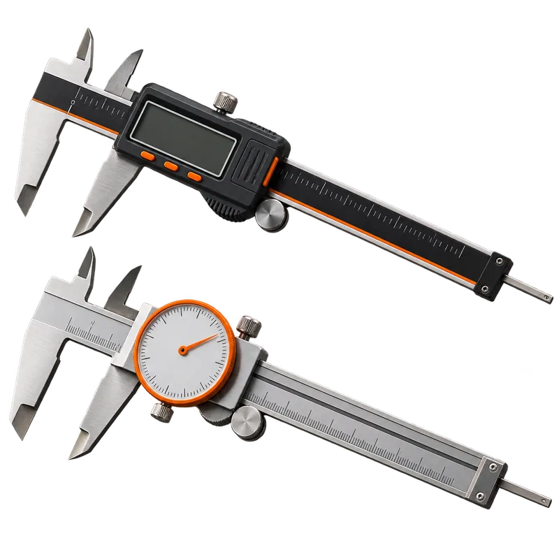
Digital and dial calipers
Make quick outside, inside, depth and step checks. Their flexibility is useful, but jaw alignment and feel limit them for very close-tolerance decisions.
Review precision-tool selection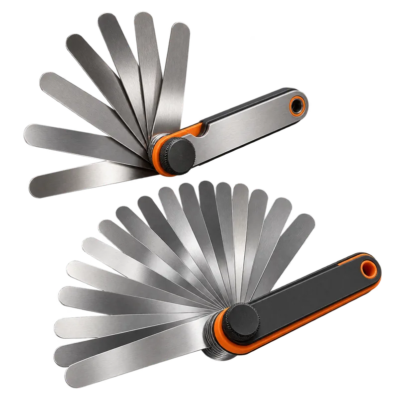
Feeler gauges
Use known blade thicknesses to check gaps, clearances and soft foot. A light, consistent drag is more reliable than forcing a blade into place.
Explore feeler gauges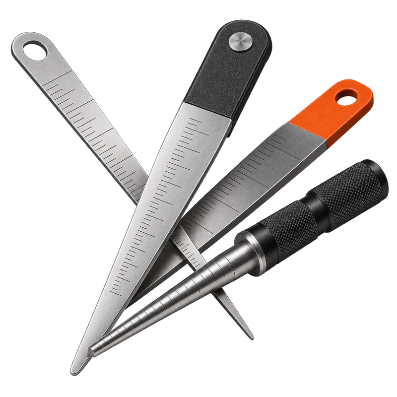
Taper gauges
Read slot width or separation at the contact line. They are fast and useful for fit-up work when inserted without wedging the parts apart.
Explore taper gauges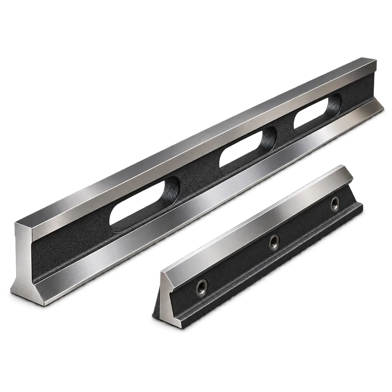
Precision straightedges
Create a trusted reference for checking flatness, light gaps and relative high or low areas. Protect the working edge from impact, corrosion and burrs.
Review precision references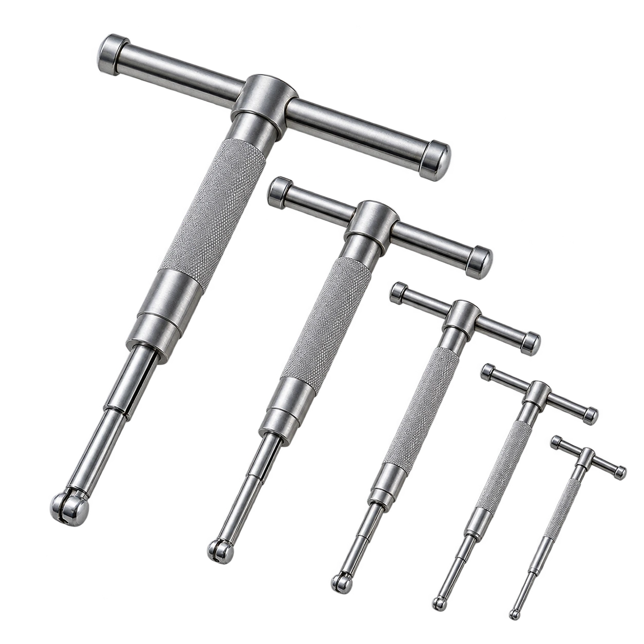
Bore gauges
Compare internal diameter and reveal taper or out-of-round condition. Set the gauge from a trusted standard and sweep through the true minimum reading.
Review range and accuracy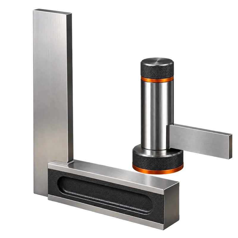
Precision squares
Check whether machine features and reference surfaces are square to one another. Clean contact faces and use an appropriate light or indicator method.
Explore selection guidanceChoose by the measurement
Match the tool to the condition you must verify
The same component may require several different checks. A coupling inspection, for example, can involve runout, face movement, gap and shaft dimensions—each requiring a different setup or instrument.
| Required check | Typical starting tool | Setup consideration |
|---|---|---|
| Runout, endplay or lift | Dial indicator with a rigid base or bracket | Preload the stem, minimize arm reach and keep contact close to the intended line of motion. |
| Shaft, journal or shim size | Outside micrometer | Use the correct frame range, clean the faces and part, and apply consistent ratchet or friction force. |
| General inside, outside or depth size | Caliper | Keep jaws square and use it for the accuracy it can support; confirm close decisions with a more suitable instrument. |
| Clearance, soft foot or narrow gap | Feeler gauge or taper gauge | Use clean, undamaged blades and avoid forcing the gauge or moving the parts being checked. |
| Machine level or slope | Machinist level | Clean the reference surface, control temperature and reverse the level in the same location to check vial error. |
| Flatness or reference geometry | Precision straightedge with light, feeler or indicator method | Support and orient the straightedge correctly; do not use a damaged working edge as a reference. |
| Bore size, taper or out-of-round | Bore gauge set from a micrometer or ring standard | Set the reference carefully and rock the gauge through the bore to locate the true minimum. |
| Squareness | Precision square with light-gap or indicator method | Keep both contact faces clean and establish which surface controls the inspection. |
A repeatable field routine
Five habits that protect the reading
Small errors stack quickly in precision work. A simple repeatable routine makes it easier to find a bad setup before it becomes a bad machinery move or an incorrect inspection record.
Clean and reference
Inspect the tool, contact surfaces, workpiece and reference before setup.
Measure and repeat
Control alignment and force, return to zero and prove that the result repeats.
Record and verify
Document units, location, condition, tolerance and the verification method used.
- Clean and inspectRemove dirt, oil films and burrs from the tool, contact point, reference and component. Check for damage, sticky movement and expired verification status.
- Establish the referenceKnow what the tool is reading from. A loose bracket, painted base, flexible cover or unknown edge cannot support a critical result.
- Control alignment and forceKeep the instrument square to the dimension or aligned with the movement. Use consistent contact force and avoid parallax on analog scales.
- Repeat or reverseReturn to zero, repeat the sweep and reverse the instrument where appropriate. A result that will not repeat is a setup problem until proven otherwise.
- Record the conditionDocument units, location, orientation, temperature or machine state when relevant, plus the tolerance and procedure used to judge the result.
Read specifications correctly
Four terms that are related—but not interchangeable
Tool listings often emphasize the smallest displayed increment. That number is useful only when the instrument's accuracy, range, condition and method support the measurement.
Resolution
- The smallest increment the tool displays or indicates
- More digits do not guarantee a truer value
- Must be considered with accuracy and repeatability
Accuracy
- How closely the result agrees with the accepted value
- May vary across the instrument's range
- Use the maker's stated accuracy, not an assumption
Sensitivity
- How much the indication responds to a change in input
- Commonly important with machinist levels
- High sensitivity also reveals vibration and setup instability
Repeatability
- How closely repeated readings agree under the same conditions
- Good repeatability does not alone prove accuracy
- Poor repeatability demands a setup or tool check
Range
- The span of values the instrument can measure
- Enough travel or capacity is required for the job
- Do not trade away needed control just for extra range
Traceability
- A documented chain connecting a measurement standard to recognized references
- Required level depends on the employer, customer and procedure
- A calibration sticker alone does not define the work method
Before, during and after the check
Verification, handling and storage
Precision instruments should be treated as measurement systems, not general hand tools. Their condition must be known before the reading and protected after the work.
Check zero and movement
Confirm smooth travel, clean contacts and a reliable zero. Use the supplied standard, a known reference or the approved verification method for the instrument.
Control temperature
Allow tools and components to stabilize when close tolerances demand it. Hand heat, sun, cold storage and recently operated equipment can shift results.
Protect measuring surfaces
Do not slide precision faces across grit, force indicator stems, bend gauge blades or place tools where vibration and falling hardware can damage them.
Store clean and dry
Wipe tools after use, apply suitable corrosion protection where required and return instruments to fitted cases with locks and contacts released.
Respect calibration controls
Follow site requirements for calibration intervals, identification, out-of-tolerance reporting and removal from service. Do not adjust controlled tools without authorization.
Question unexpected results
When a reading does not fit the machine condition, stop and inspect the setup. Recheck the reference, contact, zero, units and procedure before moving equipment.
Millwright tool questions
Frequently asked questions
Practical answers for comparing tools, planning the work and choosing equipment for the actual assignment.
Which dial indicator features matter most for shaft alignment?
Choose an indicator with suitable travel, graduation, accuracy, repeatability and mounting features for the approved alignment method. The rigid bracket, reading direction, preload, sag check and repeatability test are part of the measurement system and can matter more than brand.
Dial indicator vs dial test indicator: what is the difference?
A plunger-style dial indicator measures along the spindle axis and commonly provides more travel, while a lever-style dial test indicator measures through a pivoting contact and is useful for sensitive comparative checks in tight access. Choose the correct contact geometry and account for cosine error with lever indicators.
Why can a micrometer be more reliable than a caliper?
A micrometer uses a controlled screw mechanism and measuring faces intended for a specific measurement type and range, which can support finer resolution and repeatability. Reliability still depends on clean faces, verified standards, temperature, alignment and consistent measuring force.
How often should millwright precision tools be checked?
Check condition and zero or reference response before use and after any event that could affect accuracy. Formal calibration or verification intervals come from the employer's quality system, tool history, manufacturer guidance, required tolerance and applicable procedure.
Continue into the directory
Compare the precision tools that fit the check
Use the Precision Tools directory for detailed group guidance, field notes and exact-product comparison sections.