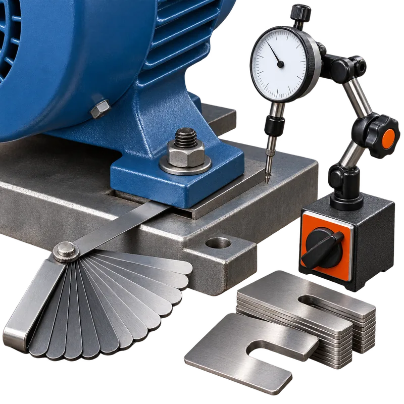
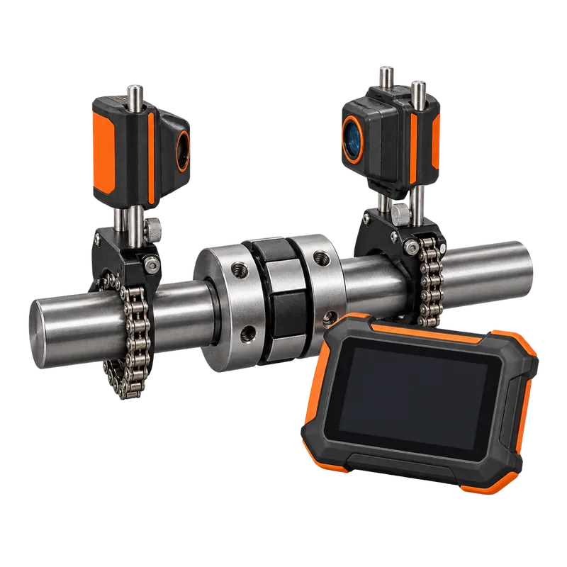
A practical directory of tools used for shaft and coupling
alignment, rough and precision alignment, soft-foot correction,
machinery leveling, positioning, runout and pipe-strain checks,
thermal-growth compensation and final verification.
Practical starting points for choosing equipment that can produce
repeatable readings and controlled machine corrections in the
field.
Laser alignment
Laser Shaft Alignment System
A paired sensor or detector system that measures the relative
position of coupled shafts and guides vertical and horizontal
machine corrections.
What the tool is used for
Measuring angular and offset misalignment and calculating
corrective moves at the movable machine feet.
Alignment work it supports
Precision shaft and coupling alignment, soft-foot routines,
live move, thermal-growth targets and final alignment
documentation.
Where it is commonly used
Pumps, motors, turbines, generators, compressors, fans,
gearboxes and other coupled rotating equipment.
Important specifications
Compare stated measurement accuracy and resolution, detector
range, measurement distance, shaft-diameter capacity,
bracket reach, inclinometer capability and environmental/IP
rating.
Buying considerations
Check mounting hardware, calibration and service support,
target/thermal-growth functions, report generation, software
licensing, battery life, accessory availability and training
requirements.
Field note
A laser can calculate the move, but it cannot fix a loose
base, pipe strain, bad coupling condition or unstable soft
foot. Correct the machine condition before chasing final
numbers.
Positioning note: Product grade, value, and price position are relative to comparable products in the same subcategory. They are not accuracy, certification, calibration, or alignment-tolerance ratings.
Compare product options
Compare Laser Shaft Alignment Systems
Compare exact manufacturer-and-model products here. Each
subgroup supports multiple manufacturers and multiple models
from the same manufacturer.
Affiliate disclosure: Some Amazon links in this section are affiliate links. I may earn a commission from qualifying purchases at no additional cost to you. As an Amazon Associate I earn from qualifying purchases.
Standard Industrial Laser Alignment Systems
Compare the verified products below. Comparison fields
include measurement method; sensor or detector configuration;
measurement range; display or controller type; wireless
communication; soft-foot functions; thermal-growth compensation;
machine-train capability; report generation; included brackets
and chains; software or app requirements; calibration and
service support. Additional comparison groups may include:
Entry-Level Laser Alignment Systems; Advanced Laser Alignment
Systems; Wireless Laser Alignment Systems; Specialty Alignment
Systems.
Exact verified product
SKF TKSA 41 Shaft Alignment Tool
Manufacturer
SKF
Model number
TKSA 41
Product type
Wireless laser shaft-alignment system
Amazon
Link available
Product grade: Professional
Intended use
Plant shaft-alignment work on standard rotating machinery
Best for
Routine pump, motor, gearbox and compressor shaft alignment
View details & specifications
Value badge: No Value PickPrice position: Higher
Why this gradeProfessional classification reflects verified construction, configuration and practical industrial use; it is not an accuracy, tolerance or calibration claim.
Value assessmentThe system offers strong alignment workflow capability, but its capital-equipment price requires a clear utilization and payback case.
Main advantageTwo wireless measurement units and a dedicated touchscreen display support live correction work
Main tradeoffDedicated hardware is a larger investment and service commitment than manual indicator methods
Information last reviewed2026-08-24
Measurement method
Two wireless measurement units; 3-position and free-measurement workflows
System measuring distance
0.07–4 m (0.23–13.1 ft)
Display
5.6 in color resistive touchscreen
Measurement error
<0.5% ±5 µm (manufacturer-published)
Functions
Live view, soft foot, automatic measurement and reporting
Power
Rechargeable LiPo batteries
Information last verified
2026-08-06
Verification note: Exact variant and listed factual specifications were checked against the source comments above. Unpublished values were not inferred, and machine/OEM/site alignment tolerances remain controlling.
Routine industrial shaft alignment with guided workflows
Best for
Maintenance teams wanting single-laser alignment with guided correction screens
View details & specifications
Value badge: No Value PickPrice position: Higher
Why this gradeProfessional classification reflects verified construction, configuration and practical industrial use; it is not an accuracy, tolerance or calibration claim.
Value assessmentThe laser workflow is capable, but the five-figure capital cost requires a clear utilization and payback case.
Main advantageSingle-laser workflow, Active Clock measurement and live correction feedback
Main tradeoffMore specialized than manual dial-indicator tooling and requires powered electronic components
Information last reviewed2026-08-24
Measurement method
Single-laser Adaptive Alignment; Active Clock measurement
Measurement positions
Up to 8 points for vertical-machine alignment
Functions
Live correction, soft foot and digital reporting
Connectivity
Wireless-enabled system
Calibration / service
Follow current Fluke service and calibration requirements
Information last verified
2026-08-06
Verification note: Exact variant and listed factual specifications were checked against the source comments above. Unpublished values were not inferred, and machine/OEM/site alignment tolerances remain controlling.
Exact verified product
Fluke 832 Laser Shaft Alignment Tool
Manufacturer
Fluke
Model number
832
Product type
Single-laser, dual-detector shaft-alignment system
Amazon
Coming soon
Product grade: Premium
Intended use
Connected industrial shaft alignment on standard machinery
Best for
Teams needing real-time correction, guided measurement and connected reporting
View details & specifications
Value badge: No Value PickPrice position: Higher
Why this gradePremium classification reflects verified construction, configuration and practical industrial use; it is not an accuracy, tolerance or calibration claim.
Value assessmentThe laser workflow is capable, but the five-figure capital cost requires a clear utilization and payback case.
Main advantageSingle laser with dual detectors, simultaneous horizontal/vertical live move and rugged tablet interface
Main tradeoffAdvanced electronics and connected workflow add cost and charging/software dependencies
Information last reviewed2026-08-24
Laser separation distance
Up to 10 m
Laser
630–640 nm, Class 2, <1 mW
Sensor / laser protection
IP65
Tablet display
8 in rugged tablet
Tablet operating time
Up to 11 hours
Functions
Live Move H/V, soft foot, thermal growth/coupling targets, reporting
Information last verified
2026-08-06
Verification note: Exact variant and listed factual specifications were checked against the source comments above. Unpublished values were not inferred, and machine/OEM/site alignment tolerances remain controlling.
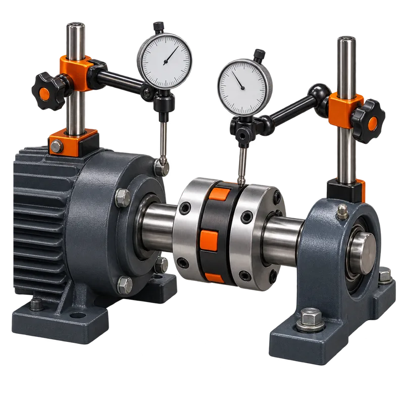
Dial alignment
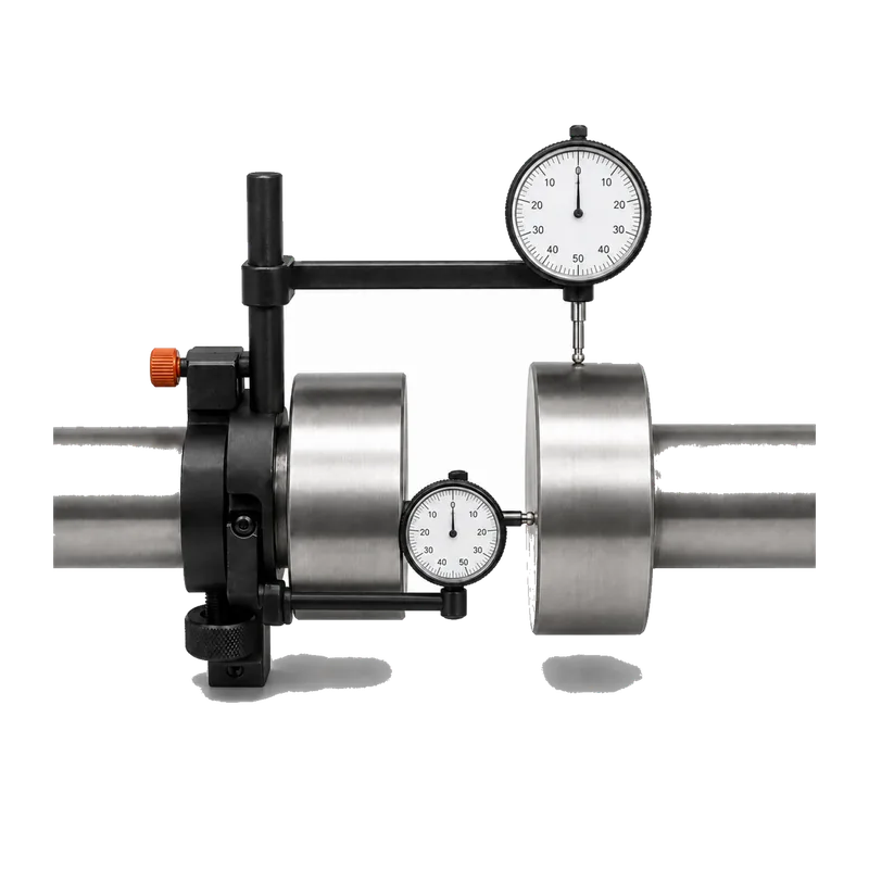
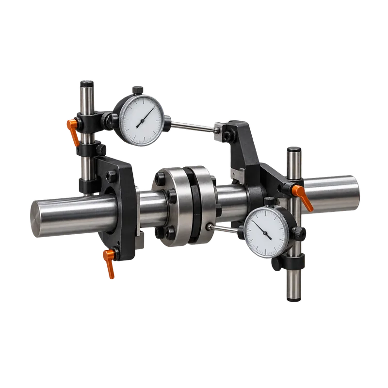
Dial Indicator Alignment Kit
A shaft-mounting fixture, rods and indicators assembled to
measure coupling or shaft position using rim-and-face or
reverse-dial methods.
What the tool is used for
Taking repeatable indicator readings through shaft rotation
to determine offset and angular misalignment.
Alignment work it supports
Rim-and-face, reverse-dial, shaft runout checks, coupling
checks and precision alignment where dial methods are
specified or preferred.
Where it is commonly used
Motor-pump sets, compressors, fans, gearboxes, turbines and
coupled machinery in plants, shops and outage work.
Important specifications
Common indicators read 0.001 inch per division;
closer-resolution instruments may be used when required.
Check indicator travel, rod length, shaft diameter range,
bracket rigidity and mounting-chain capacity.
Buying considerations
Look for rigid brackets, fine adjustment, low-sag rods,
compatible indicator stems, enough reach for the coupling
geometry and replaceable mounting parts.
Field note
Before recording readings, rotate the complete setup and check
for bracket sag, loose joints and indicator sticking. A
perfect calculation is only as good as the fixture holding the
indicator.
Compare product options
Compare Dial Indicator Alignment Kits
Compare exact manufacturer-and-model products here. Each
subgroup supports multiple manufacturers and multiple models
from the same manufacturer.
Affiliate disclosure: Some Amazon links in this section are affiliate links. I may earn a commission from qualifying purchases at no additional cost to you. As an Amazon Associate I earn from qualifying purchases.
Complete Dual-Indicator Kits
Compare the verified products below. Comparison fields
include indicator quantity; indicator range; indicator
resolution; bracket construction; bar length; chain or mounting
capacity; sag-control features; included rods and accessories;
storage case; replacement-part availability. Additional
comparison groups may include: Rim-and-Face Alignment Kits; Reverse-Dial
Alignment Kits; Compact Alignment Kits; Specialty Bracket
Systems.
Exact verified product
Starrett S668DZ Shaft Alignment Clamp Set
Manufacturer
Starrett
Model number
S668DZ / EDP 67153
Product type
Complete Dual-Indicator Kits
Amazon
Link available
Product grade: Professional
Intended use
Traditional dual-indicator shaft-alignment work
Best for
Rim/face or indicator-based checks on motors, pumps and compressors
View details & specifications
Value badge: No Value PickPrice position: Higher
Why this gradeProfessional classification reflects verified construction, configuration and practical industrial use; it is not an accuracy, tolerance or calibration claim.
Value assessmentThe rigid alignment-clamp system is useful, but its premium price is best justified by frequent dial-indicator alignment work.
Main advantageComplete matched fixture package includes two 81-141J indicators, clamps, posts and case
Main tradeoffManual indicator alignment requires careful setup, rotation, sag awareness and calculation discipline
Verification note: Exact variant and listed factual specifications were checked against the source comments above. Unpublished values were not inferred, and machine/OEM/site alignment tolerances remain controlling.
Users who prefer Starrett 196B5 indicators in the 668 clamp system
View details & specifications
Value badge: No Value PickPrice position: Higher
Why this gradeProfessional classification reflects verified construction, configuration and practical industrial use; it is not an accuracy, tolerance or calibration claim.
Value assessmentThe rigid alignment-clamp system is useful, but its premium price is best justified by frequent dial-indicator alignment work.
Main advantageComplete 668-series package includes two 196B5 indicators and fitted case
Main tradeoffManual two-indicator setup is more technique-dependent than guided electronic systems
Information last reviewed2026-08-24
Kit type
Complete dual-indicator shaft-alignment clamp set
Indicators
2 × Starrett 196B5
Chain clamps
2
Shaft capacity
Up to 7-1/2 in diameter
Posts
5 in, 7-7/16 in and 9 in lengths
Other included hardware
PT18724 snugs, extension plates and posts
Case
Fitted case included
Information last verified
2026-08-06
Verification note: Exact variant and listed factual specifications were checked against the source comments above. Unpublished values were not inferred, and machine/OEM/site alignment tolerances remain controlling.
Accushim SK-2D Shaft-to-Shaft Alignment Kit with Gauges
Manufacturer
Accushim
Model number
ACC-SK-2D
Product type
Complete Dual-Indicator Kits
Amazon
Coming soon
Product grade: Professional
Intended use
Starter reverse-indicator shaft-to-shaft alignment work
Best for
Smaller coupled machines needing a complete two-indicator starter fixture
View details & specifications
Value badge: Value PickPrice position: Higher
Why this gradeProfessional classification reflects verified construction, configuration and practical industrial use; it is not an accuracy, tolerance or calibration claim.
Value assessmentThe complete dual-indicator kit costs more than basic fixtures but offers a ready professional alignment system with documented components.
Main advantageIncludes two AGD Group 1 indicators plus stainless mounting hardware and case
Main tradeoff3.5 in maximum shaft diameter and 6 in maximum span limit larger applications
Information last reviewed2026-08-24
Kit type
Shaft-to-shaft alignment starter kit
Indicators
2 × DI-3 AGD Group 1 mini dial indicators
Maximum shaft diameter
3.5 in
Maximum shaft-to-shaft span
6 in
Mounting hardware
Two 6 in bracket bases, chains, rods and indicator clamps
Case
Carrying case included
Information last verified
2026-08-06
Verification note: Exact variant and listed factual specifications were checked against the source comments above. Unpublished values were not inferred, and machine/OEM/site alignment tolerances remain controlling.
Indicator supports
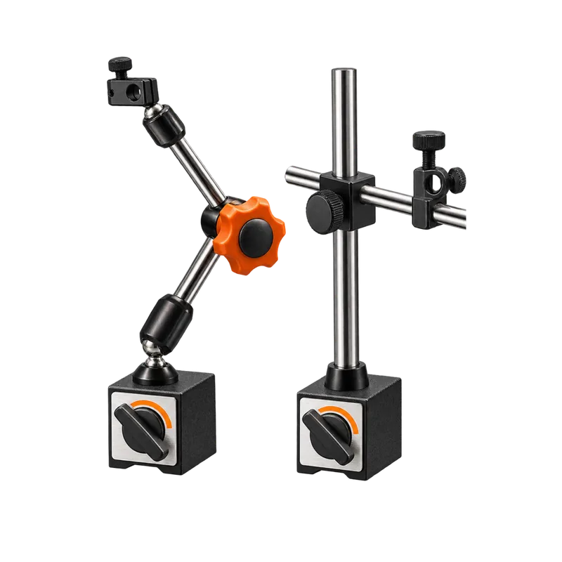
Magnetic Indicator Base
A switchable magnetic base and adjustable arm used to hold an
indicator rigidly relative to a ferrous reference surface.
What the tool is used for
Holding dial or test indicators for shaft, hub, coupling,
endplay and relative-movement measurements.
Machine bases, bearing housings, coupling guards removed for
work, shop setups and ferrous equipment frames.
Important specifications
Check holding force, arm reach, fine-adjust location, base
footprint, stem/dovetail compatibility and articulation
range.
Buying considerations
Favor rigidity and repeatability over maximum reach. Confirm
the base fits the available landing area and that
replacement arms, clamps and contact hardware are
obtainable.
Field note
Clean the magnet and landing surface, lock every joint and
give the arm a light stability check before zeroing. Dirt
under the base can become movement at the needle.
Compare product options
Compare Magnetic Indicator Bases
Compare exact manufacturer-and-model products here. Each
subgroup supports multiple manufacturers and multiple models
from the same manufacturer.
Affiliate disclosure: Some Amazon links in this section are affiliate links. I may earn a commission from qualifying purchases at no additional cost to you. As an Amazon Associate I earn from qualifying purchases.
Articulating-Arm Bases
Compare the verified products below. Comparison fields
include manufacturer-confirmed magnetic holding force; base
dimensions; arm reach; articulation; fine adjustment; indicator
stem or lug-back compatibility; on/off magnetic control;
rigidity; overall weight. Additional comparison groups may
include: Standard Post-and-Arm Bases; Fine-Adjustment Bases;
Low-Profile Bases; Heavy-Duty Magnetic Bases.
Exact verified product
Noga MG61003 MG Holder
Manufacturer
Noga
Model number
MG61003
Product type
Articulated magnetic indicator holder
Amazon
Link available
Product grade: Professional
Intended use
Heavy-duty indicator positioning for machinery checks
Best for
Dial or test-indicator setups needing a strong switchable magnetic base and central locking arm
View details & specifications
Value badge: Value PickPrice position: Moderate
Why this gradeProfessional classification reflects verified construction, configuration and practical industrial use; it is not an accuracy, tolerance or calibration claim.
Value assessmentThe price is well aligned with a rigid professional magnetic holder that can improve setup speed and repeatability.
Main advantage800 N published magnet force with central locking and top fine adjustment
Main tradeoff1.90 kg assembly is heavier than compact articulated holders
Information last reviewed2026-08-24
Magnet force
800 N
Magnet size
50 × 60 × 55 mm
Arm lengths
133 mm bottom / 113 mm top
Total length
317 mm
Clamp compatibility
6 mm, 8 mm, 3/8 in and dovetail
Fine adjustment
Top fine adjustment; central locking mechanism
Weight
1.90 kg
Information last verified
2026-08-06
Verification note: Exact variant and listed factual specifications were checked against the source comments above. Unpublished values were not inferred, and machine/OEM/site alignment tolerances remain controlling.
Setups where extra lower-arm reach is useful around couplings or machine structure
View details & specifications
Value badge: Value PickPrice position: Moderate
Why this gradeProfessional classification reflects verified construction, configuration and practical industrial use; it is not an accuracy, tolerance or calibration claim.
Value assessmentThe price is well aligned with a rigid professional magnetic holder that can improve setup speed and repeatability.
Main advantage163.5 mm lower arm with the same 800 N published magnetic force and universal top clamp
Main tradeoffLarger 1.95 kg assembly takes more setup space than standard-length holders
Information last reviewed2026-08-24
Magnet force
800 N
Magnet size
50 × 60 × 55 mm
Arm lengths
163.5 mm bottom / 113 mm top
Clamp compatibility
6 mm, 8 mm, 3/8 in and dovetail
Fine adjustment
Top fine adjustment; central locking mechanism
Weight
1.95 kg
Information last verified
2026-08-06
Verification note: Exact variant and listed factual specifications were checked against the source comments above. Unpublished values were not inferred, and machine/OEM/site alignment tolerances remain controlling.
General dial/test-indicator work needing a lighter central-locking magnetic holder
View details & specifications
Value badge: Value PickPrice position: Moderate
Why this gradeProfessional classification reflects verified construction, configuration and practical industrial use; it is not an accuracy, tolerance or calibration claim.
Value assessmentThe price is well aligned with a rigid professional magnetic holder that can improve setup speed and repeatability.
Main advantage800 N published magnet force with 282 mm total length at 1.35 kg
Main tradeoffShorter arms provide less reach than MG-series heavy-duty holders
Information last reviewed2026-08-24
Magnet force
800 N
Magnet size
50 × 60 × 55 mm
Arm lengths
110 mm bottom / 101 mm top
Total length
282 mm
Clamp compatibility
6 mm, 8 mm, 3/8 in and dovetail
Fine adjustment
Top fine adjustment; central locking mechanism
Weight
1.35 kg
Information last verified
2026-08-06
Verification note: Exact variant and listed factual specifications were checked against the source comments above. Unpublished values were not inferred, and machine/OEM/site alignment tolerances remain controlling.
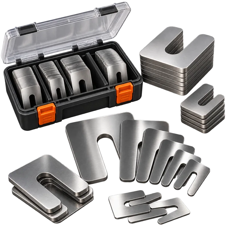
Slotted, thickness-marked machinery shims used under equipment
feet to make controlled vertical alignment and soft-foot
corrections.
What the tool is used for
Raising machine feet by measured amounts while maintaining a
stable, clean bearing surface under each foot.
Alignment work it supports
Vertical shaft alignment, soft-foot correction, machinery
leveling and final equipment positioning.
Where it is commonly used
Motors, pumps, bearing pedestals, gearboxes, compressors and
other base-mounted rotating equipment.
Important specifications
Select shim footprint and slot width for the hold-down bolt
and machine foot. Kits commonly include multiple
thousandths-of-an-inch thicknesses; verify actual marked
thickness and material grade.
Buying considerations
Choose corrosion-resistant stock with deburred edges and
permanently marked thicknesses. Keep enough sizes and
duplicates to avoid excessive stacking.
Field note
Clean beneath the foot and replace damaged, painted or burred
shims. Use the fewest practical layers so the stack stays
solid when the hold-down bolt is torqued.
Compare product options
Compare Pre-Cut Stainless Steel Shim Kits
Compare exact manufacturer-and-model products here. Each
subgroup supports multiple manufacturers and multiple models
from the same manufacturer.
Affiliate disclosure: Some Amazon links in this section are affiliate links. I may earn a commission from qualifying purchases at no additional cost to you. As an Amazon Associate I earn from qualifying purchases.
Standard Machinery Shim Kits
Compare the verified products below. Comparison fields
include shim dimensions; slot width; material grade; thickness
range; thickness identification; number of pieces; case
organization; replacement-pack availability; burr control and
edge finish. Additional comparison groups may include:
Small-Footprint Shim Kits; Large-Footprint Shim Kits; Metric
Shim Kits; Imperial Shim Kits; Mixed-Thickness Replacement
Packs.
Exact verified product
Accushim Size A Mini Shim Kit
Manufacturer
Accushim
Model number
A-MINI KIT
Product type
Machinery Shim Kits
Amazon
Coming soon
Product grade: Professional
Intended use
Routine inch-size machinery foot shimming
Best for
Compact 2 × 2 in shim assortment for common small-to-medium motor feet
View details & specifications
Value badge: Value PickPrice position: Moderate
Why this gradeProfessional classification reflects verified construction, configuration and practical industrial use; it is not an accuracy, tolerance or calibration claim.
Value assessmentThe organized stainless mini-shim assortment offers good value by reducing field cutting and sorting time.
Main advantage130-piece Type 304/18-8 stainless assortment covers 13 published thicknesses in a metal box
Main tradeoff2 × 2 in Size A footprint and 5/8 in slot are not suitable for larger feet or hold-down bolts
Verification note: Exact variant and listed factual specifications were checked against the source comments above. Unpublished values were not inferred, and machine/OEM/site alignment tolerances remain controlling.
Exact verified product
SKF TMAS 50/KIT Machinery Shim Kit
Manufacturer
SKF
Model number
TMAS 50/KIT
Product type
Machinery Shim Kits
Amazon
Link available
Product grade: Professional
Intended use
Metric machinery alignment and height adjustment
Best for
Machine feet suited to the 50 × 50 mm shim footprint
View details & specifications
Value badge: No Value PickPrice position: Higher
Why this gradeProfessional classification reflects verified construction, configuration and practical industrial use; it is not an accuracy, tolerance or calibration claim.
Value assessmentThe organized stainless shim assortment saves field time, but the premium kit price is best justified by repeated alignment work.
Main advantageManufacturer-defined 50 mm system with clearly marked 304S31 stainless pre-cut shims
Main tradeoffMetric 50 mm footprint and 13 mm slot must match the machine foot and bolt geometry
Information last reviewed2026-08-24
Kit type
Metric pre-cut machinery shim kit
Shim size
50 × 50 mm
Slot width
13 mm
Material
304S31 stainless steel
Thickness range
0.05–2.00 mm in the kit assortment
Marking
Thickness marked on each shim
Storage
Kit case
Information last verified
2026-08-06
Verification note: Exact variant and listed factual specifications were checked against the source comments above. Unpublished values were not inferred, and machine/OEM/site alignment tolerances remain controlling.
Multi-size metric machinery shimming in plant maintenance
Best for
Maintenance teams supporting multiple machine-foot sizes from one organized metric kit
View details & specifications
Value badge: No Value PickPrice position: Higher
Why this gradeProfessional classification reflects verified construction, configuration and practical industrial use; it is not an accuracy, tolerance or calibration claim.
Value assessmentThe broad organized shim inventory saves field time, but the premium kit price requires repeated alignment use.
Main advantageCombines multiple 50, 75 and 100 mm shim sizes in one dedicated case
Main tradeoffLarger multi-size kit is less compact than a single-footprint assortment
Information last reviewed2026-08-24
Kit type
Multi-size metric machinery shim assortment
Shim sizes
50 × 50, 75 × 75 and 100 × 100 mm
Material
304S31 stainless steel
Thickness assortment
0.05, 0.10, 0.20, 0.25, 0.40, 0.50, 0.70, 1.00 and 2.00 mm
Marking
Thickness marked on each shim
Case dimensions
530 × 110 × 360 mm
Information last verified
2026-08-06
Verification note: Exact variant and listed factual specifications were checked against the source comments above. Unpublished values were not inferred, and machine/OEM/site alignment tolerances remain controlling.
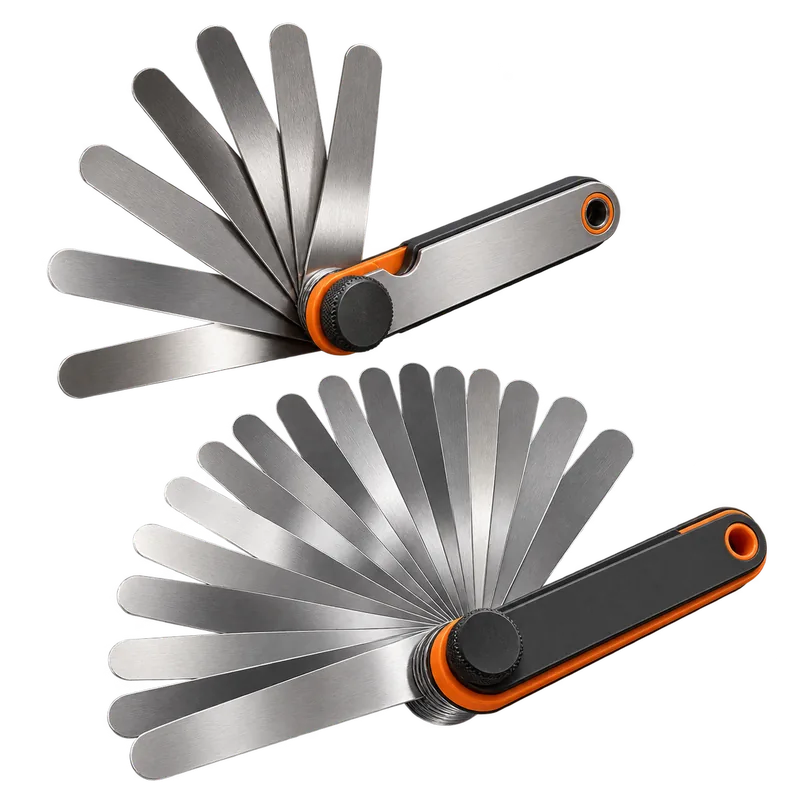
A set of accurately sized thin blades used individually or
stacked to check small gaps beneath machine feet and between
fitted surfaces.
What the tool is used for
Measuring gaps during soft-foot inspection and checking
coupling, flange and fitted-part clearances.
Alignment work it supports
Soft-foot detection and correction, rough coupling checks,
pipe-strain investigation and installation verification.
Where it is commonly used
Machine feet and bases, coupling faces, pipe flanges,
bearing fits and general machinery setup.
Important specifications
Sets commonly span about 0.0015 to 0.035 inch. Compare blade
increments, inch/metric markings, blade length, tip shape
and material.
Buying considerations
Use clear permanent markings and choose stainless, brass or
nonmagnetic blades where the work environment calls for
them.
Field note
Use a light, repeatable drag and check more than one point
around the foot when diagnosing angular soft foot. Do not
force a blade and create the gap you are trying to measure.
Compare product options
Compare Feeler Gauge Sets
Compare exact manufacturer-and-model products here. Each
subgroup supports multiple manufacturers and multiple models
from the same manufacturer.
Affiliate disclosure: Some Amazon links in this section are affiliate links. I may earn a commission from qualifying purchases at no additional cost to you. As an Amazon Associate I earn from qualifying purchases.
Standard Straight-Blade Sets
Compare the verified products below. Comparison fields
include measurement range; blade count; blade length; blade
width; material; etched or stamped markings; locking mechanism;
replaceable blades; corrosion resistance. Additional comparison
groups may include: Long-Blade Feeler Gauges; Tapered-Blade
Feeler Gauges; Offset Feeler Gauges; Metric Sets; Imperial Sets;
Mixed Metric and Imperial Sets.
Exact verified product
Proto J000TL 25-Blade Long Feeler Gauge Set
Manufacturer
Proto
Model number
J000TL
Product type
Straight-blade feeler / thickness gage
Amazon
Link available
Product grade: Professional
Intended use
Long-reach gap and clearance checks
Best for
Alignment and soft-foot checks where 12-inch blades improve reach
View details & specifications
Value badge: Value PickPrice position: Moderate
Why this gradeProfessional classification reflects verified construction, configuration and practical industrial use; it is not an accuracy, tolerance or calibration claim.
Value assessmentThe long 25-blade set offers useful reach and a competitive professional-tool price for recurring clearance checks.
Main advantage25 stainless 12-inch blades with decimal and metric-equivalent etching
Main tradeoffLong blades are bulkier than compact pocket-style sets
Information last reviewed2026-08-24
Blade count
25
Thickness range
0.0015–0.040 in
Blade size
1/2 × 12 in
Material
Stainless steel blades; steel holder
Markings
Decimal size and metric equivalent etched on blades
Product weight
0.72 lb
Information last verified
2026-08-06
Verification note: Exact variant and listed factual specifications were checked against the source comments above. Unpublished values were not inferred, and machine/OEM/site alignment tolerances remain controlling.
Routine alignment-preparation checks where a compact inch set is preferable
View details & specifications
Value badge: Value PickPrice position: Moderate
Why this gradeProfessional classification reflects verified construction, configuration and practical industrial use; it is not an accuracy, tolerance or calibration claim.
Value assessmentThe price is reasonable for a durable multi-blade thickness-gage set used repeatedly for clearance and gap checks.
Main advantage26 straight tempered-steel leaves cover a dense common inch range
Main tradeoffShorter leaves provide less reach than long-blade sets
Information last reviewed2026-08-24
Blade count
26
Thickness range
0.0015–0.025 in
Blade style
Straight leaves
Blade length
3-1/32 in
Material
Tempered steel
Individual calibration
Not published by manufacturer
Information last verified
2026-08-06
Verification note: Exact variant and listed factual specifications were checked against the source comments above. Unpublished values were not inferred, and machine/OEM/site alignment tolerances remain controlling.
Users wanting detachable, marked straight blades in a compact 3-inch format
View details & specifications
Value badge: Value PickPrice position: Moderate
Why this gradeProfessional classification reflects verified construction, configuration and practical industrial use; it is not an accuracy, tolerance or calibration claim.
Value assessmentThe price is reasonable for a durable multi-blade thickness-gage set used repeatedly for clearance and gap checks.
Main advantageEach leaf is marked with its thickness and detachable
Main tradeoff3-inch blades offer less reach than long-blade field sets
Information last reviewed2026-08-24
Blade count
26
Thickness range
0.0015–0.035 in
Blade style
Straight; 1/2 in wide
Blade length
3 in
Leaf marking
Each leaf marked with thickness
Leaf thickness tolerance
Varies by nominal thickness; manufacturer publishes separate tolerance bands
Information last verified
2026-08-06
Verification note: Exact variant and listed factual specifications were checked against the source comments above. Unpublished values were not inferred, and machine/OEM/site alignment tolerances remain controlling.
Rough alignment
Precision Straightedge
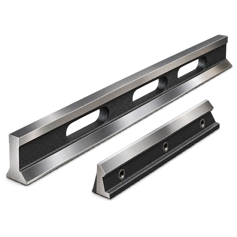
A verified straight reference edge placed across coupling rims
or machine surfaces for quick comparative alignment and flatness
checks.
What the tool is used for
Establishing rough coupling alignment, checking relative rim
position and identifying obvious high spots, gaps or surface
deviation.
Alignment work it supports
Initial shaft and coupling setup, pre-alignment positioning,
base and soleplate inspection and general reference checks.
Where it is commonly used
Couplings, fabricated bases, soleplates, machine feet and
installation reference surfaces.
Important specifications
Choose a length that bridges the surfaces being compared and
verify the manufacturer’s straightness tolerance, edge
geometry, material and corrosion protection.
Buying considerations
A general shop rule is not a precision straightedge. Match
the certified or stated straightness to the job and protect
the reference edge in storage.
Field note
A straightedge is excellent for getting a coupling close
enough for precision measurement; do not treat a light-gap
check as a substitute for the required final alignment method.
Compare product options
Compare Precision Straightedges
Compare exact manufacturer-and-model products here. Each
subgroup supports multiple manufacturers and multiple models
from the same manufacturer.
Affiliate disclosure: Some Amazon links in this section are affiliate links. I may earn a commission from qualifying purchases at no additional cost to you. As an Amazon Associate I earn from qualifying purchases.
Ground Steel Straightedges
Compare the verified products below. Comparison fields
include length; cross-section; material; manufacturer-confirmed
straightness tolerance; working-edge configuration; weight;
handling features; storage case; calibration or certification
availability. Additional comparison groups may include: Beveled
Straightedges; Cast-Iron Straightedges; Aluminum Precision
Straightedges; Short Inspection Straightedges; Long Machinery
Straightedges.
Exact verified product
Starrett 380-12 Steel Straight Edge
Manufacturer
Starrett
Model number
380-12
Product type
Ground steel straightedge
Amazon
Link available
Product grade: Professional
Intended use
Portable reference-edge checks during machinery setup
Best for
Checking smaller machine surfaces for straightness before or during setup
View details & specifications
Value badge: Value PickPrice position: Moderate
Why this gradeProfessional classification reflects verified construction, configuration and practical industrial use; it is not an accuracy, tolerance or calibration claim.
Value assessmentThe current price is reasonable for a verified 12-inch steel straightedge used for setup and inspection checks.
Main advantage12-inch precision-ground steel reference edge is portable and ungraduated
Main tradeoffShort nominal length cannot bridge the larger spans addressed by longer straightedges
Information last reviewed2026-08-24
Nominal length
12 in
Series
Starrett 380
Material
Steel
Edge / scale configuration
Precision-ground; not beveled; not graduated
Manufacturer-described use
Checking surfaces for straightness and precision layout
Numerical straightness tolerance
Not published on the exact product page reviewed
Information last verified
2026-08-06
Verification note: Exact variant and listed factual specifications were checked against the source comments above. Unpublished values were not inferred, and machine/OEM/site alignment tolerances remain controlling.
Machine bases and components needing a 36-inch portable reference edge
View details & specifications
Value badge: No Value PickPrice position: Higher
Why this gradeProfessional classification reflects verified construction, configuration and practical industrial use; it is not an accuracy, tolerance or calibration claim.
Value assessmentThe verified precision straightedge is capable, but its premium price limits value for occasional setup checks.
Main advantageLonger 36-inch ground working edge bridges surfaces the 12-inch model cannot
Main tradeoffLonger steel straightedges demand more careful handling and support to limit deflection
Information last reviewed2026-08-24
Nominal length
36 in
Series
Starrett 380
Material
Steel
Edge / scale configuration
Precision-ground; not beveled; not graduated
Support guidance
Manufacturer marks suspension points on 36 in and longer models
Numerical straightness tolerance
Not published on exact page reviewed
Information last verified
2026-08-06
Verification note: Exact variant and listed factual specifications were checked against the source comments above. Unpublished values were not inferred, and machine/OEM/site alignment tolerances remain controlling.
Starrett 385-18 Steel Straight Edge with Bevel Edge
Manufacturer
Starrett
Model number
385-18
Product type
Ground steel straightedge with bevel edge
Amazon
Coming soon
Product grade: Professional
Intended use
Ground reference-edge and fine-edge surface comparison
Best for
Checks where an 18-inch straightedge with one beveled working edge improves access or visibility
View details & specifications
Value badge: No Value PickPrice position: Higher
Why this gradeProfessional classification reflects verified construction, configuration and practical industrial use; it is not an accuracy, tolerance or calibration claim.
Value assessmentThe beveled precision straightedge is capable, but its premium price limits value for occasional checks.
Main advantageOne beveled edge provides a finer reference profile than the non-beveled 380 series
Main tradeoffBeveled edge adds handling sensitivity and still does not replace a documented tolerance/inspection method
Information last reviewed2026-08-24
Nominal length
18 in
Series
Starrett 385
Material
Steel
Edge / scale configuration
Precision-ground; one beveled edge; not graduated
Manufacturer-described use
Checking surfaces for straightness and precision layout
Numerical straightness tolerance
Not published on exact page reviewed
Information last verified
2026-08-06
Verification note: Exact variant and listed factual specifications were checked against the source comments above. Unpublished values were not inferred, and machine/OEM/site alignment tolerances remain controlling.
Machinery leveling
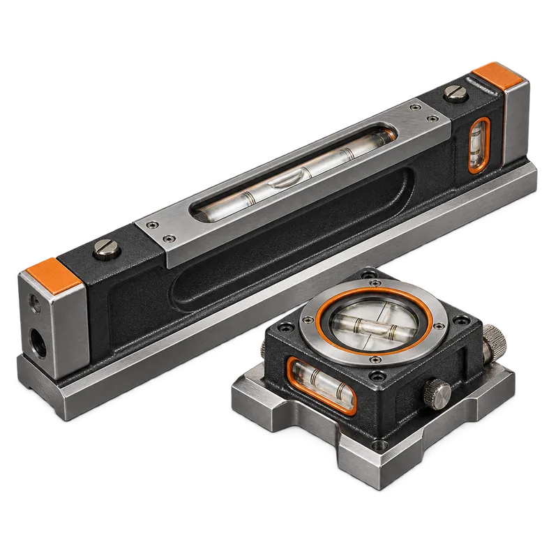
Machinist Level
A sensitive precision level used to detect very small changes in
machine elevation and slope across reference surfaces.
What the tool is used for
Leveling baseplates, soleplates, machine ways, bearing
housings and specified reference surfaces before or during
alignment.
Alignment work it supports
Machinery installation, base setup, preliminary geometry
checks and alignment preparation where level is an
installation requirement.
Sensitivity may be stated per division, such as 0.0005 inch
per foot. Common lengths include 6, 8 and 12 inches; confirm
base style, cross-level vial and calibration method.
Buying considerations
Match sensitivity and length to the specified work. Look for
a ground base, protected adjustable vial and dependable
calibration/service support.
Field note
Clean the reference surface and let the level stabilize
thermally. Reverse it in the same location to identify level
error before making a machine move.
Compare product options
Compare Machinist Levels
Compare exact manufacturer-and-model products here. Each
subgroup supports multiple manufacturers and multiple models
from the same manufacturer.
Affiliate disclosure: Some Amazon links in this section are affiliate links. I may earn a commission from qualifying purchases at no additional cost to you. As an Amazon Associate I earn from qualifying purchases.
Standard Machinist Levels
Compare the verified products below. Comparison fields
include length; sensitivity; vial or electronic display; base
configuration; V-groove; cross level; adjustment method;
temperature considerations; calibration or verification support;
storage case. Additional comparison groups may include: Compact
Machinist Levels; Master Precision Levels; Adjustable Precision
Levels; Electronic Precision Levels.
Exact verified product
Starrett 98-6 Machinists Level
Manufacturer
Starrett
Model number
98-6
Product type
Machinist / precision level
Amazon
Link available
Product grade: Professional
Intended use
Compact machinery leveling and round-work checks
Best for
Machine bases and shafting where a compact 6-inch level fits the contact area
View details & specifications
Value badge: No Value PickPrice position: Higher
Why this gradeProfessional classification reflects verified construction, configuration and practical industrial use; it is not an accuracy, tolerance or calibration claim.
Value assessmentPrecision-level capability is credible, but the premium price requires frequent high-sensitivity leveling work to justify.
Main advantage6-inch body with cross-test vial and grooved base for round work
Main tradeoffShort contact length is less suitable when a longer reference surface is required
Information last reviewed2026-08-24
Nominal length
6 in
Sensitivity / graduation
0.005 in per foot per graduation
Main vial
Adjustable graduated vial
Cross-test vial
Yes
Base
Machined cast iron; longitudinal involute groove
Recommended operating temperature
40–120 °F
Information last verified
2026-08-06
Verification note: Exact variant and listed factual specifications were checked against the source comments above. Unpublished values were not inferred, and machine/OEM/site alignment tolerances remain controlling.
General machine-base leveling on longer contact surfaces
Best for
Equipment bases with enough continuous surface for a 12-inch reference
View details & specifications
Value badge: No Value PickPrice position: Higher
Why this gradeProfessional classification reflects verified construction, configuration and practical industrial use; it is not an accuracy, tolerance or calibration claim.
Value assessmentThe master-level construction is appropriate for precision work, but the premium price limits its value outside frequent high-accuracy leveling.
Main advantageLonger 12-inch base while retaining the 98-series cross-vial and grooved-base format
Main tradeoffRequires a longer continuous contact surface than the 6-inch model
Information last reviewed2026-08-24
Nominal length
12 in
Sensitivity / graduation
0.005 in per foot per graduation
Cross-test vial
Yes
Base
Machined cast iron; longitudinal groove
Base width
1-7/16 in
Product weight
3.3 lb
Information last verified
2026-08-06
Verification note: Exact variant and listed factual specifications were checked against the source comments above. Unpublished values were not inferred, and machine/OEM/site alignment tolerances remain controlling.
Precision longitudinal and transverse surface leveling
Best for
Machine setup where both longitudinal and transverse vial readings are useful
View details & specifications
Value badge: No Value PickPrice position: Higher
Why this gradeProfessional classification reflects verified construction, configuration and practical industrial use; it is not an accuracy, tolerance or calibration claim.
Value assessmentPrecision-level capability is credible, but the premium price requires frequent high-sensitivity leveling work to justify.
Main advantageHigh-precision longitudinal and transverse vials in one instrument
Main tradeoffMore specialized than a compact general machinist level
Information last reviewed2026-08-24
Sensitivity
0.0012 in per 12 in
Manufacturer-published accuracy
±0.0006 in
Dimensions
7.87 × 1.73 × 1.50 in
Vials
Longitudinal and transverse
Case
Wooden box supplied
Calibration / traceability
Not published by manufacturer in source reviewed
Information last verified
2026-08-06
Verification note: Exact variant and listed factual specifications were checked against the source comments above. Unpublished values were not inferred, and machine/OEM/site alignment tolerances remain controlling.
Gap measurement
Taper Gauge
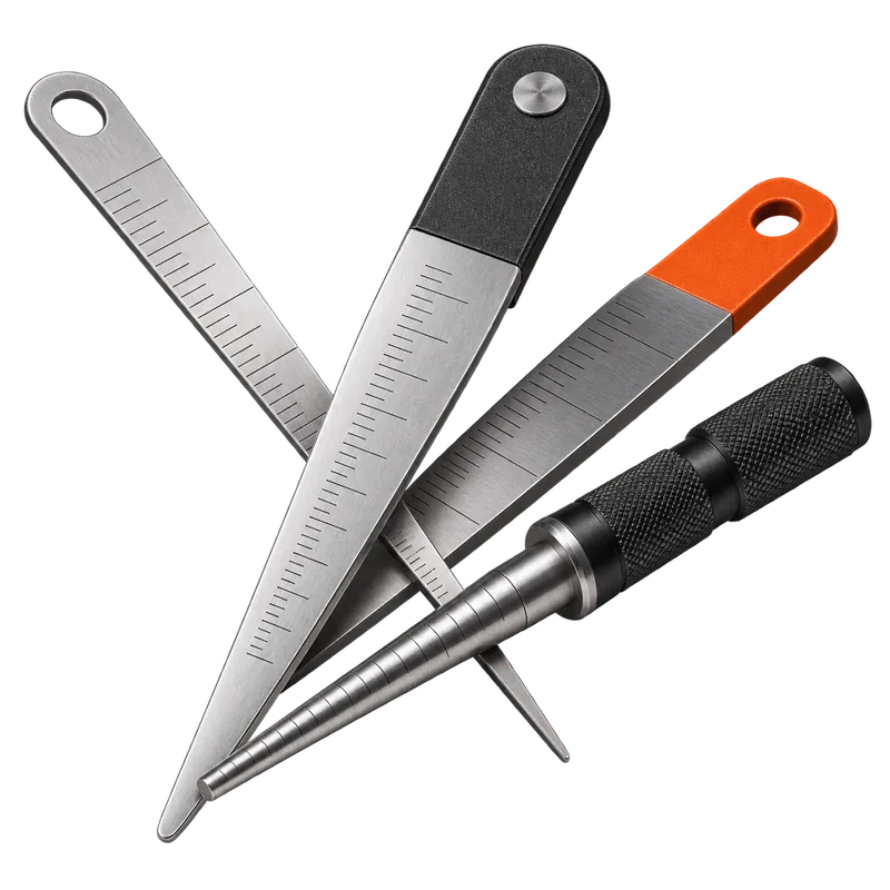
A graduated wedge inserted into an accessible gap to make a fast
direct reading of separation or slot width.
What the tool is used for
Checking coupling gaps, flange separation, slots, bearing
split lines and other accessible gaps during setup and
inspection.
Alignment work it supports
Rough coupling alignment, flange and pipe-strain checks,
machinery setup and verification of accessible gaps.
Where it is commonly used
Coupling faces, piping flanges, casing joints, machinery
feet and shop or field fit-up work.
Important specifications
Common inch ranges are roughly 0.010 to 0.150 inch, while
metric gauges may cover about 0.4 to 6 mm. Check graduation
spacing, thickness, range and scale legibility.
Buying considerations
Select a blade geometry and range that can reach the
measuring point without forcing the parts apart. Etched
graduations generally hold up better in field service.
Field note
Slide the gauge in without wedging the joint open and read
exactly where the edge contacts the scale. For critical final
values, use the method required by the job procedure.
Compare product options
Compare Taper Gauges
Compare exact manufacturer-and-model products here. Each
subgroup supports multiple manufacturers and multiple models
from the same manufacturer.
Affiliate disclosure: Some Amazon links in this section are affiliate links. I may earn a commission from qualifying purchases at no additional cost to you. As an Amazon Associate I earn from qualifying purchases.
Dual-Scale Taper Gauges
Compare the verified products below. Comparison fields
include measurement range; scale type; graduations; material;
blade thickness; etched markings; protective case; included
companion gauges. Additional comparison groups may include:
Standard Taper Gauges; Long-Range Taper Gauges; Metric Taper
Gauges; Imperial Taper Gauges; Taper-Gauge and Feeler-Gauge
Sets.
Exact verified product
Starrett 270 Taper Gage
Manufacturer
Starrett
Model number
270
Product type
Dual-scale taper gage
Amazon
Link available
Product grade: Professional
Intended use
Direct slot, gap and bearing-work checks
Best for
Fast alignment-related gap checks in inch or metric units
View details & specifications
Value badge: No Value PickPrice position: Higher
Why this gradeProfessional classification reflects verified construction, configuration and practical industrial use; it is not an accuracy, tolerance or calibration claim.
Value assessmentThe precision taper range is useful, but the premium price is hard to justify unless this exact inspection task is routine.
Main advantageSingle tapered blade carries inch and metric scales
Main tradeoff0.010-inch lower limit does not cover the smallest feeler-gauge clearances
Information last reviewed2026-08-24
Measurement range
0.010–0.150 in / 0.3–4 mm
Graduations
0.001 in / 0.05 mm
Material
Tool steel
Dimensions
7/16 in wide × 6-1/4 in long
Scale style
Inch on one side; metric on reverse
Manufacturer-described use
Bearing work and gaging slots
Information last verified
2026-08-06
Verification note: Exact variant and listed factual specifications were checked against the source comments above. Unpublished values were not inferred, and machine/OEM/site alignment tolerances remain controlling.
Technicians wanting a hardened stainless dual-scale wedge for roughly 1–15 mm openings
View details & specifications
Value badge: Value PickPrice position: Lower
Why this gradeProfessional classification reflects verified construction, configuration and practical industrial use; it is not an accuracy, tolerance or calibration claim.
Value assessmentThe low price and compact dual-scale taper format provide useful field value for quick gap checks.
Main advantageUS scale on one side and metric on the opposite side with manufacturer-published accuracy
Main tradeoffRange starts around 1/16 in / 1 mm, so smaller clearances need a different gauge
Information last reviewed2026-08-24
Measurement range
1/16–5/8 in / 1–15 mm
Manufacturer-published accuracy
±0.002 in / ±0.05 mm
Material
Hardened stainless steel
Body size
5-43/64 × 43/64 × 3/64 in (148 × 17 × 1.2 mm)
Scale style
US on one side; metric on opposite side
Information last verified
2026-08-06
Verification note: Exact variant and listed factual specifications were checked against the source comments above. Unpublished values were not inferred, and machine/OEM/site alignment tolerances remain controlling.
Exact verified product
Linear Tools Stainless Steel Taper Gauge
Manufacturer
Linear Tools
Model number
53-888-006
Product type
Dual-scale stainless taper gauge
Amazon
Coming soon
Product grade: General Purpose
Intended use
Routine dual-scale slot, bore and gap checks
Best for
General maintenance checks where both metric and fractional-inch wedge scales are useful
View details & specifications
Value badge: Value PickPrice position: Moderate
Why this gradeGeneral Purpose classification reflects verified construction, configuration and practical industrial use; it is not an accuracy, tolerance or calibration claim.
Value assessmentThe stainless construction and readable taper scale justify a modest midrange price for recurring gap measurement.
Main advantageSimple stainless dual-scale wedge covers 1–16 mm and 1/64–5/8 in scales
Main tradeoffPublished fractional-inch scale is coarser than thousandth-inch taper gauges
Information last reviewed2026-08-24
Metric scale
1–16 mm in 0.1 mm increments
Inch scale
1/64–5/8 in in 1/64 in increments
Material
Stainless steel
Scale style
Metric front; inch reverse
Manufacturer-described use
Cylindrical bores, bearing work and slots
Accuracy
Not published in sources reviewed
Information last verified
2026-08-06
Verification note: Exact variant and listed factual specifications were checked against the source comments above. Unpublished values were not inferred, and machine/OEM/site alignment tolerances remain controlling.
Selection & verification reminder: Match the alignment method and equipment to the machine, required tolerance, measurement range and mounting conditions. Verify instrument condition and calibration status where required, check setup rigidity and bracket sag, and follow the approved alignment procedure and manufacturer instructions.
From inspection to final readings
Typical Machinery Alignment Workflow
A general sequence for preparing, measuring, correcting and
verifying a coupled machine alignment.
Inspect the machine and baseConfirm the equipment is ready for alignment and the working
area and reference surfaces are usable.
Check for obvious damage or loosenessLook for loose fasteners, damaged feet, base problems, coupling
issues and other conditions that can defeat a stable
alignment.
Perform rough alignmentBring shafts and coupling geometry close enough for the
selected precision measurement method.
Check and correct soft footIdentify feet that rock, lift or distort the frame and correct
the condition before final shaft corrections.
Measure shaft or coupling alignmentCollect readings with the approved laser, reverse-dial,
rim-and-face or other specified method.
Calculate or enter correctionsUse the approved calculation or alignment-system workflow to
determine required machine-foot moves.
Move the machine horizontally and verticallyUse clean shims for vertical corrections and controlled jacking
or positioning tools for horizontal moves.
Tighten hold-down boltsTighten in the required sequence and watch for movement caused
by bolt tightening.
Recheck alignmentTake a fresh set of readings after tightening to confirm the
machine remains within the required condition.
Document final readingsRecord final values, targets, machine condition and other
documentation required by the facility or work package.
Procedure reminder
Actual alignment procedures, tolerances, acceptance criteria and
thermal-growth targets must follow the equipment manufacturer,
facility requirements and the instructions for the alignment
system being used.
Before you buy
Select the alignment system for the work you actually do.
The best kit is the one that can mount securely, measure the
machine geometry, survive the environment and produce the accuracy
and documentation your jobs require.
Required accuracy: Match instrument accuracy and
system capability to the actual acceptance tolerance.
Shaft diameter & coupling size: Confirm
brackets, chains and sensors fit the equipment you service.
Available mounting space: Check sensor
dimensions, bracket reach and clearance through the full
measurement rotation.
Measurement distance: Verify the system can
handle the sensor-to-sensor or indicator span required by the
machine.
Magnetic vs. chain mounting: Magnetic fixtures
are fast on suitable ferrous surfaces; chain-mounted shaft
brackets fit a wider range of shaft arrangements.
Laser vs. dial methods: Laser systems speed
calculation and reporting; dial methods remain versatile,
transparent and useful where specified.
Environmental protection: Consider water, oil,
dust, temperature, drops and the IP rating of electronic
equipment.
Calibration support: Check service intervals,
certificates, turnaround time and traceability requirements.
Replacement parts: Price chains, rods, brackets,
cables, batteries, chargers and common wear or loss items.
Software & reports: Confirm target entry,
thermal-growth compensation, saved jobs, exports and report
formats match the facility workflow.
Training requirements: Budget for competent setup
and method training, not just the instrument.
Cost vs. frequency of use: A high-end system
earns its place faster on frequent precision work; occasional work
may favor a simpler, serviceable setup.
Millwright tool questions
Frequently asked questions
Practical answers for comparing tools, planning the work and choosing equipment for the actual assignment.
Laser shaft alignment vs dial indicators: which method is better?
Laser systems can simplify measurement, calculation, live moves and documentation, while dial methods remain effective when the setup geometry, bracket sag, indicator travel and calculations are controlled. The approved procedure, machine geometry, available access, technician competence and required records determine the suitable method.
What is the best dial indicator setup for shaft alignment?
The best setup is rigid, repeatable and compatible with the selected rim-and-face or reverse-dial method. Choose adequate indicator travel and graduation, minimize bracket sag and looseness, establish correct preload and reading direction, and perform repeatability checks before calculating moves.
SKF TKSA 41 vs Fluke 831: how should a millwright compare them?
Compare the SKF TKSA 41 and Fluke 831 by measurement workflow, shaft and coupling access, detector range, live-move guidance, reporting, ruggedness, software support and calibration requirements. Select against the machinery program and documentation needs rather than choosing only by purchase price.
Which tools are needed for a soft-foot check?
A soft-foot check commonly uses the approved alignment system or dial indicator, clean feeler gauges, suitable shims, torque tools and cleaning supplies. Measure before correcting, distinguish parallel from angular or induced conditions, and follow the machine and alignment procedure for limits and bolt sequence.
New and improved across the directory
Recently updated and related
Jump from the directory into the most useful supporting guide, related method or reviewed product group.