Field-tested information for industrial millwrightsExperience in the trade since 1995

Move. Set. Level. Align.

Machinery installation tools for millwrights

A practical directory for receiving, moving, setting, leveling, anchoring, grouting and aligning pumps, motors, compressors, turbines, generators and other industrial machinery.

View featured installation tools
16 installation tool groups

Installation methods depend on equipment weight, geometry, foundation design, engineering documents, manufacturer instructions and site procedures. Select tools for the actual job—not by category name alone.

Installation sequence

Tools through the machinery installation process

The actual sequence is controlled by drawings, equipment instructions and the site plan. This overview shows where common millwright tools typically enter the work.

  1. Receive and inspect the equipmentUse approved unloading rigging, inspection tools, documentation, measuring tools and protective materials to verify condition and identify shipping damage before the move.
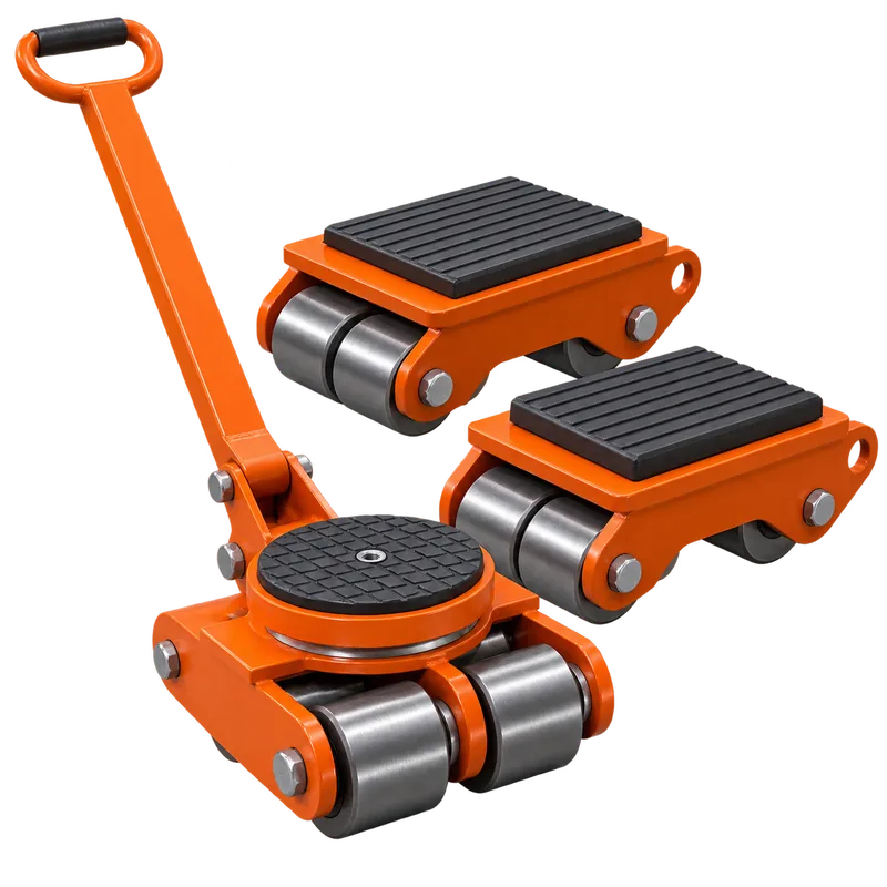
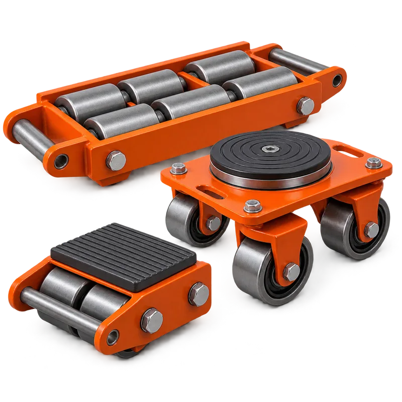
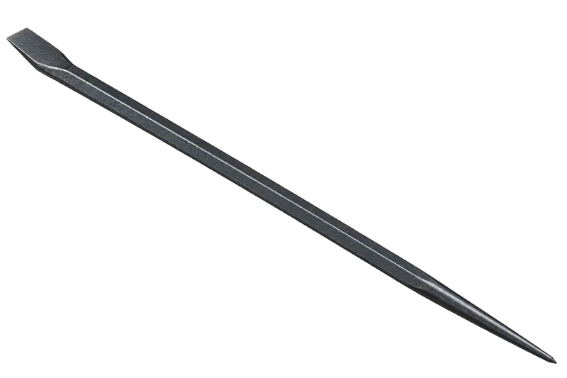
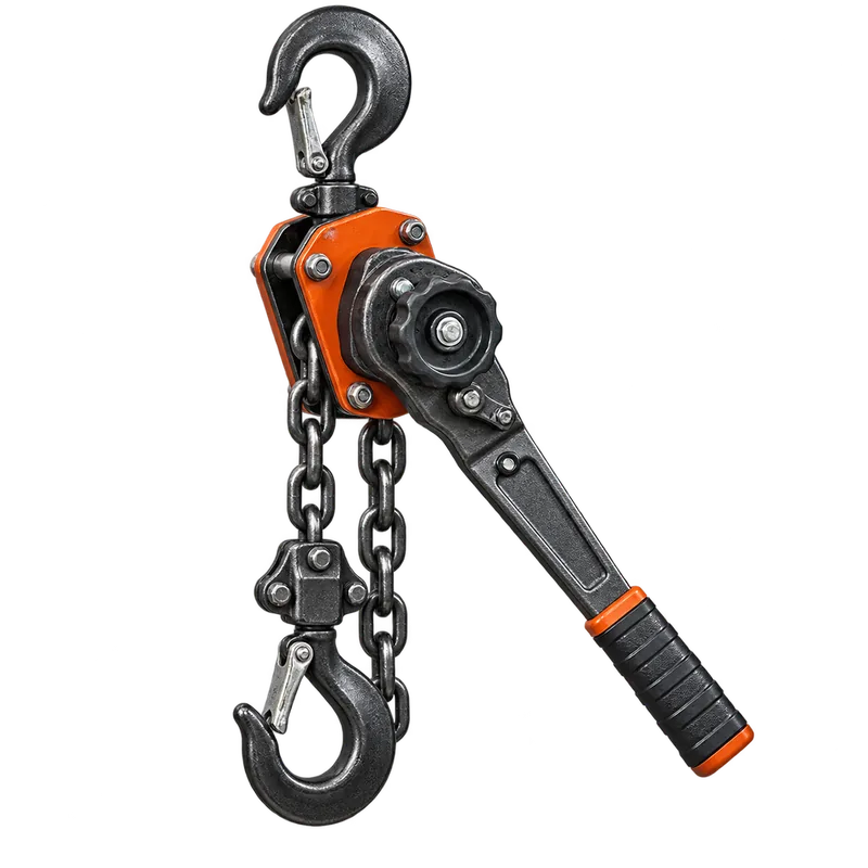
  2. Move the equipment into the work areaMachinery skates, roller dollies, approved positioning hoists, pry/alignment bars and rigging equipment support a planned travel route suited to the verified weight and center of gravity.
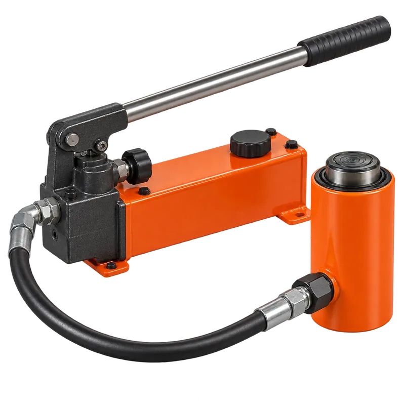
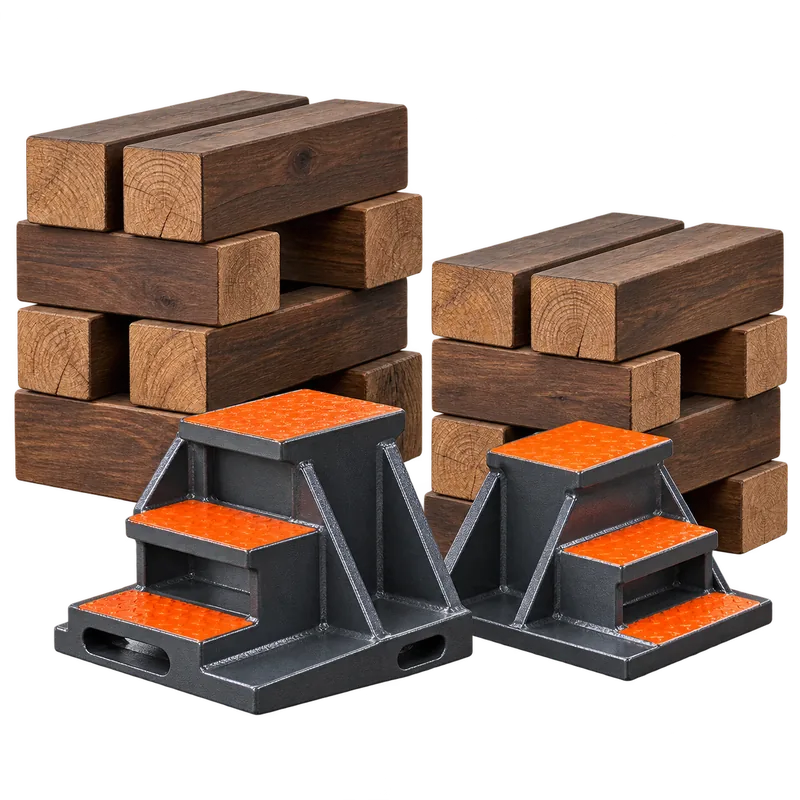
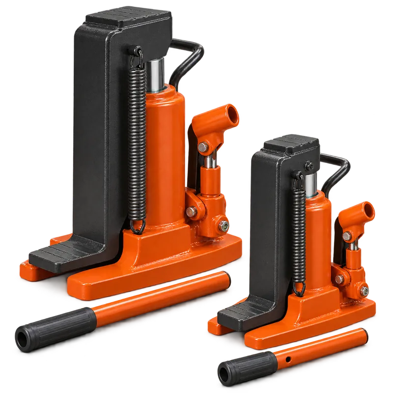
  3. Lift, block and support the equipmentRated toe jacks, hydraulic rams and approved rigging may raise the machine; approved blocking or cribbing provides support before personnel enter an exposure area.
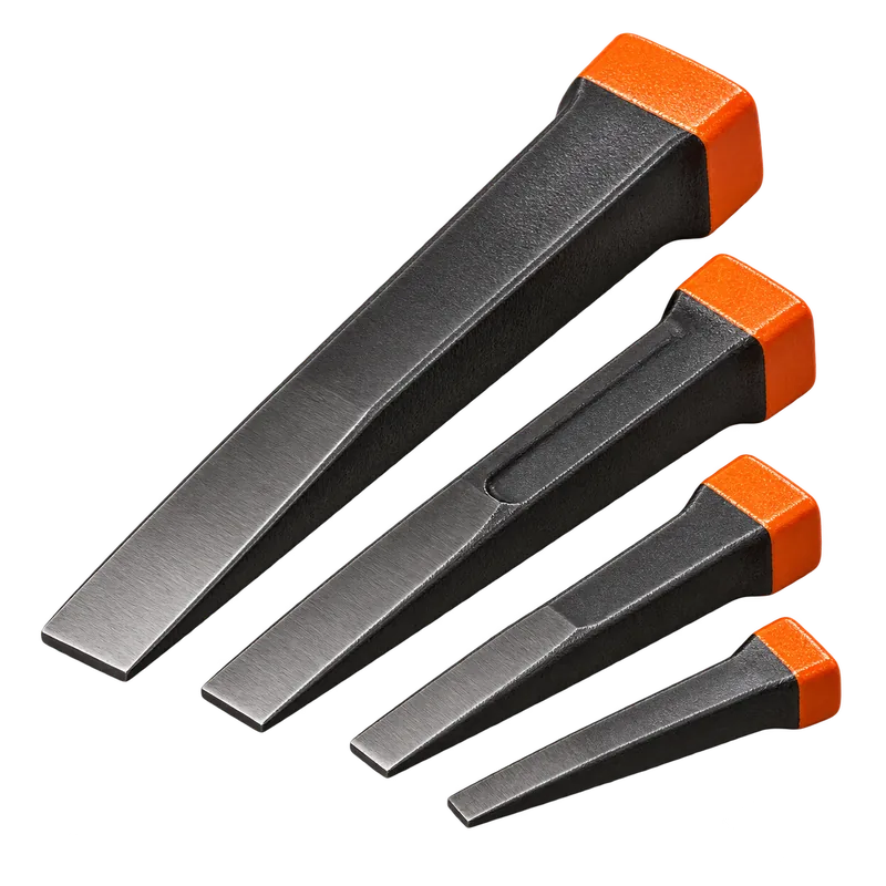
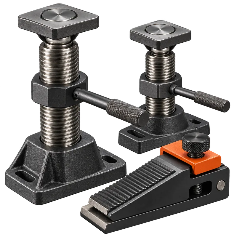
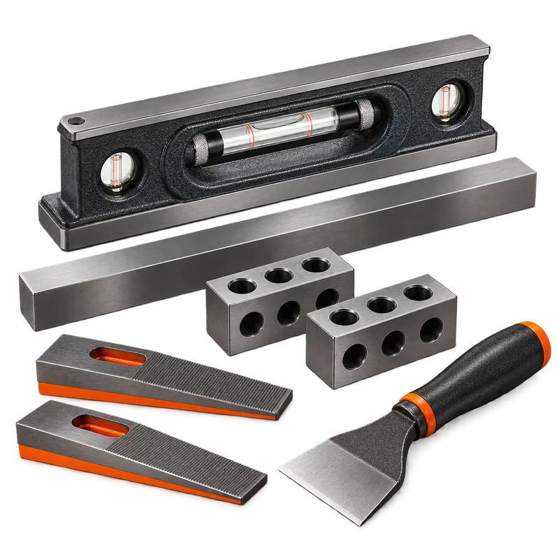
  4. Position the base or skidJack screws, wedges, bars, positioning hoists, levels and layout/measurement tools help establish location, orientation and initial elevation.
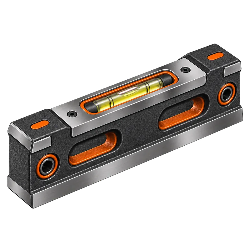
  5. Rough-level the machineryPrecision levels, approved wedges, jack/leveling screws and suitable support points help bring the base into the project’s rough-level tolerance.
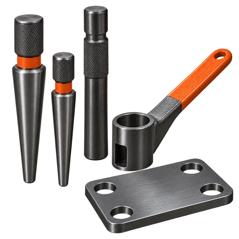
  6. Install and position anchor boltsTemplates, layout/measurement tools, levels and approved anchor-positioning hardware help establish location, projection and geometry from the engineering documents.
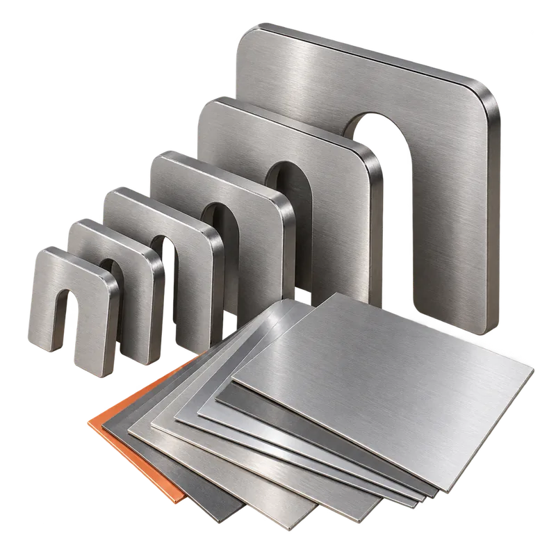
  7. Shim and prepare for groutingStainless shims, precision levels, feeler gauges and specified base/foundation preparation tools support elevation control and surface readiness before grouting.
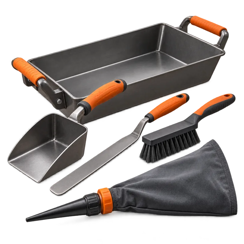
  8. Place and finish groutSpecified mixing, measuring, placement and finishing tools support the grout manufacturer’s required batching, flow, placement and curing procedure.
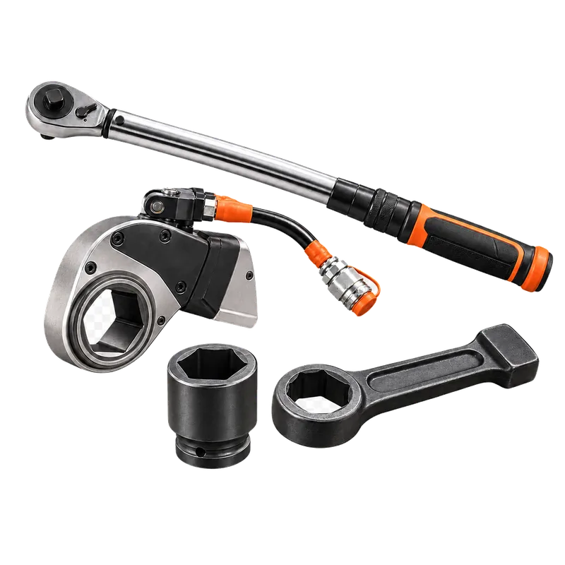
  9. Perform final levelingPrecision levels, shims, jack screws where permitted, torque/bolting tools and dial indicators support final checks after the foundation system reaches the required condition.
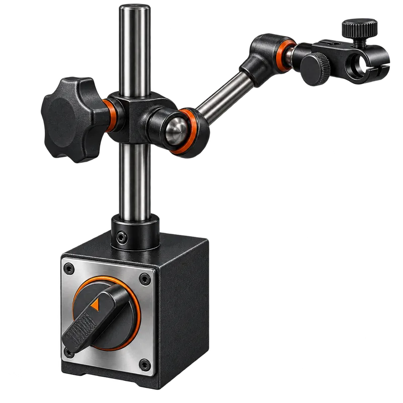
  10. Complete shaft or coupling alignmentLaser or dial-indicator alignment tools, magnetic bases, feeler gauges and shims support final alignment to the equipment manufacturer and project tolerances.
Sequence varies by installation.

Some equipment arrives on common skids, uses soleplates, requires specialty grout or follows OEM procedures that change these stages. Engineering and manufacturer documents control.

Safety & field guidance

Plan the support, route and setup before the move.

Heavy machinery stores a lot of energy even when it is only inches off the floor. These reminders supplement—not replace—training, procedures or lift planning.

  • Support before exposure: Machinery must be supported with approved blocking before personnel work beneath it or enter an area where loss of support could expose them.
  • Stay within ratings: Toe jacks, rams, pumps, hoses, couplers and other hydraulic equipment must be used within their rated capacities and manufacturer instructions.
  • Verify contact points: Toe-jack and ram contact points must be structurally suitable for the intended force and approved setup.
  • Use suitable travel surfaces: Machinery skates and roller dollies require a suitable, clean and level travel surface capable of supporting the loads and compatible with their rollers, steering and travel.
  • Evaluate the move: Confirm equipment weight, center of gravity, load distribution, clearances, floor capacity and the complete travel path before movement.
  • Account for load distribution: Do not assume equal loading at every jack, skate or dolly; capacity selection must reflect the actual weight distribution and center of gravity.
  • Control multiple lift points: Multiple lifting points can require coordinated or engineered procedures. Keep hands and feet clear of pinch and crush zones throughout the work.
  • Use adjustment tools only as intended: Temporary wedges are not substitutes for approved permanent supports, and jack screws must not be treated as lifting devices unless they are specifically designed and rated for that use.
  • Follow the installation documents: Anchor-bolt location, baseplate support, grout selection/placement and final tolerances must follow engineering documents and manufacturer instructions.
  • Follow lifting requirements: Lifting and rigging work must follow site procedures, manufacturer requirements and applicable regulations.
This directory is not an engineered lifting or machinery-moving plan.

No single jack, skate, dolly, hoist or other tool is suitable for every installation. Qualified personnel must select and use equipment for the specific load, conditions and approved procedure.

Millwright tool questions

Frequently asked questions

Practical answers for comparing tools, planning the work and choosing equipment for the actual assignment.

What is a hydraulic toe jack used for in machinery installation?

A toe jack lifts from a low engagement point so machinery can be raised enough for approved blocking, shimming or placement of moving equipment. Verify capacity at the toe position, engagement, surface stability, lift height and manufacturer instructions, and never rely on hydraulic pressure alone to support the load.

Hilman HTJ-508 vs HTJ-1009: how should I compare toe jacks?

Compare rated toe and head capacities, minimum toe height, stroke, base footprint, jack weight and the machine access available. Choose from the verified load and lift plan; a higher-capacity jack is not automatically safer if it cannot engage or sit correctly.

How do machinery skates work safely?

Machinery skates carry a supported load over a clean, level surface using a planned path and controlled push or pull. Confirm load distribution, skate capacity, steering, floor loading, slope, obstructions, pinch points, braking and communication before movement.

When should a millwright use shims, wedges or jack screws?

Use these tools according to the baseplate and installation design: jack screws or wedges can support controlled positioning, while measured shims establish durable support where specified. Keep contact stable, avoid excessive shim layers and complete grouting, anchor tightening and alignment in the approved sequence.

Continue browsing

Build the complete machinery installation setup.

Move from positioning equipment into the hand tools, precision measurement, alignment, rigging and consumables that support the full installation.