
Machinery installation field guide
Machinery Installation & Baseplate Setup
A practical sequence for receiving, lifting, moving, setting, leveling and preparing industrial machinery for grouting, final alignment and turnover—without treating any single tool as the plan.
Field guide: https://millwrightsupply.com/machinery-installation-field-guide.html
The equipment arrives into a prepared system
Confirm the job basis and foundation readiness
Machinery installation begins before the machine is lifted. Drawings, foundation data, access, utilities, lifting information, baseplate details and the required final condition must agree with what is physically present.
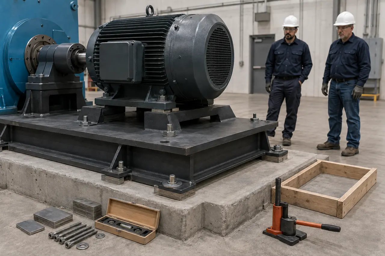
Each layer must carry load as designed
Equipment information
- Verified weight and center of gravity
- Approved lift and support points
- Shipping braces, loose parts and preservation condition
Foundation condition
- Released concrete or structural support
- Elevation, dimensions, pockets and embeds checked
- Surface condition and grout space match the design
Baseplate and anchors
- Correct base, soleplates and hardware received
- Anchor bolts positioned, protected and serviceable
- Adjustment provisions and grout details understood
Access and route
- Doorways, floor loading and overhead clearance verified
- Travel path clean, stable and controlled
- Landing and temporary support prepared
Interfaces
- Driver, driven equipment and coupling requirements identified
- Piping, conduit, guards and auxiliaries sequenced
- External strain will not be used to pull the machine into place
Work controls
- Lift/move plan and qualified roles assigned
- Hazardous energy and stored energy addressed
- Inspection, hold points and turnover records defined
Do not make the machine compensate for a foundation, baseplate, anchor-bolt or interface problem. Identify the mismatch and resolve it through the approved engineering and quality process.
A controlled progression
Typical machinery-installation sequence
Prepare
Release the foundation, verify drawings and stage the approved move and support system.
Set and support
Establish orientation, elevation and stable load transfer without forcing the machine.
Align and turn over
Grout, connect, recheck machine condition and document the as-left result.
- Review drawings and proceduresConfirm orientation, reference lines, elevations, anchor details, baseplate requirements, grout system, tolerances and hold points.
- Receive and inspectDocument shipping condition, identification, preservation, loose components, damage, shaft restraint and any storage requirements.
- Prepare the work areaVerify foundation release, clean access, floor capacity, lifting route, laydown space, tools, blocking and environmental controls.
- Lift and transferUse the approved rigging and machinery-moving plan to place the machine on prepared temporary or final supports.
- Establish rough positionOrient to centerlines, anchor bolts, coupling relationship and elevation without forcing the machine or connected systems.
- Level and supportUse approved shims, wedges, leveling screws, soleplates or chocks so the load is stable and the base is not distorted.
- Check machine conditionInspect feet, base contacts, soft foot, shaft/coupling condition, runout concerns and response to controlled bolt tightening.
- Prepare and place groutRelease only after formwork, cleanliness, support, mixing, temperature, placement and cure controls match the specified grout system.
- Align and connectComplete required shaft alignment and interface work in the specified sequence while controlling pipe, conduit and base strain.
- Verify and turn overConfirm final readings, fasteners, supports, grout status, guards, lubrication, preservation removal, documentation and unresolved punch items.
Tools support the sequence
Core machinery-installation tool groups
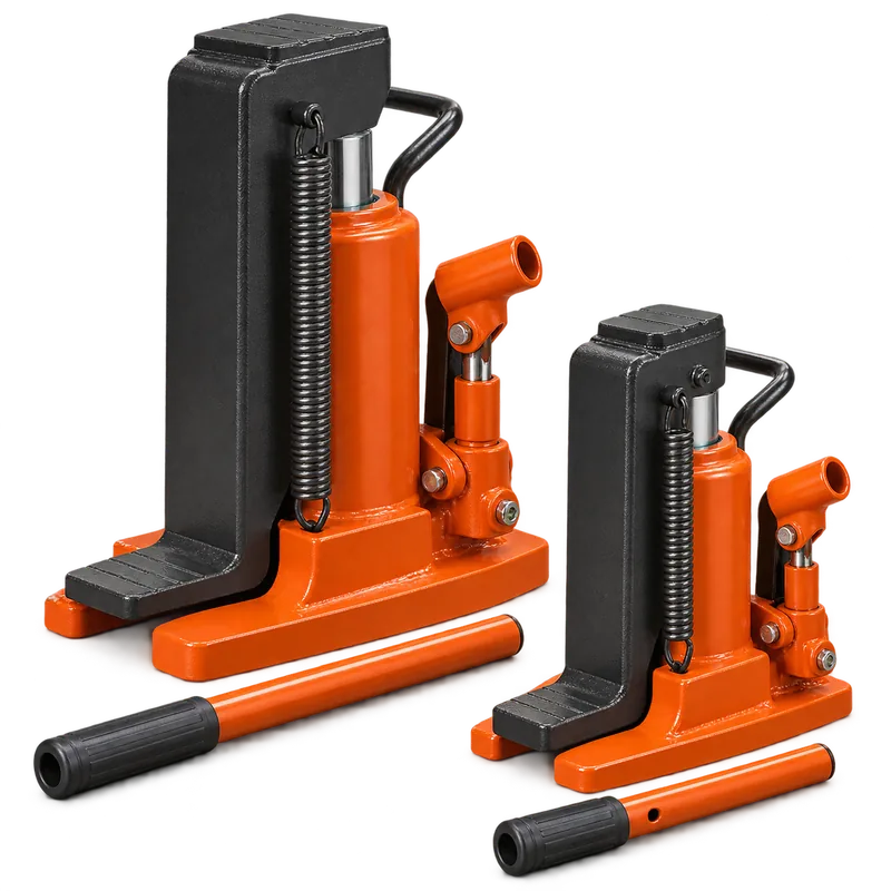
Hydraulic toe jacks
Lift from low access points so blocking or rollers can be installed. Capacity, lift point, base support and load stability must be confirmed.
Explore toe jacks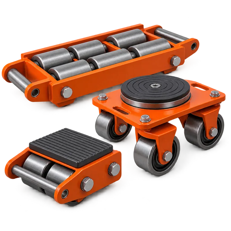
Rollers and dollies
Move loads over suitable, verified surfaces. Select the configuration for load distribution, steering, route condition and secure attachment.
Explore rollers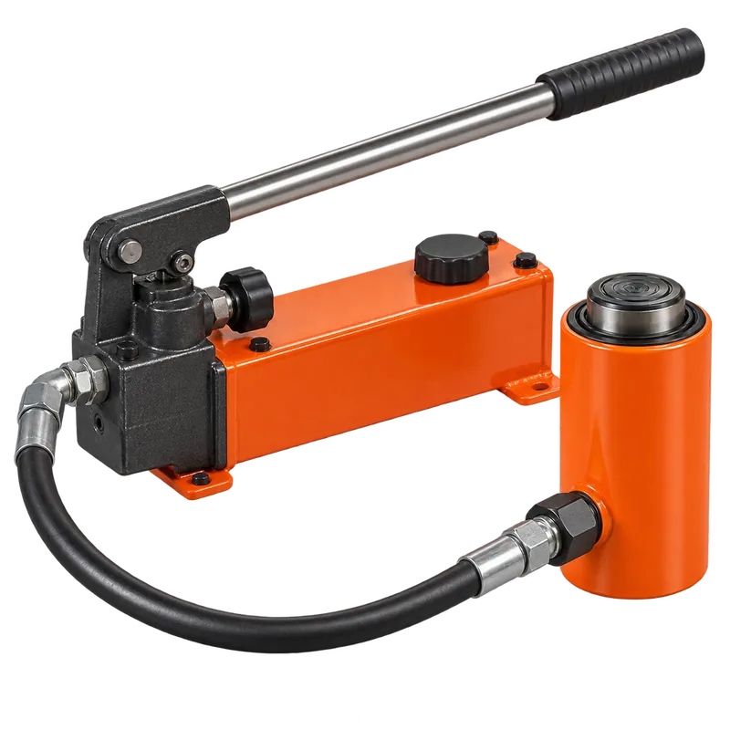
Hydraulic rams and pumps
Apply controlled force only through suitable reaction points. Match components, inspect hoses and fittings and keep people out of the line of force.
Explore hydraulic sets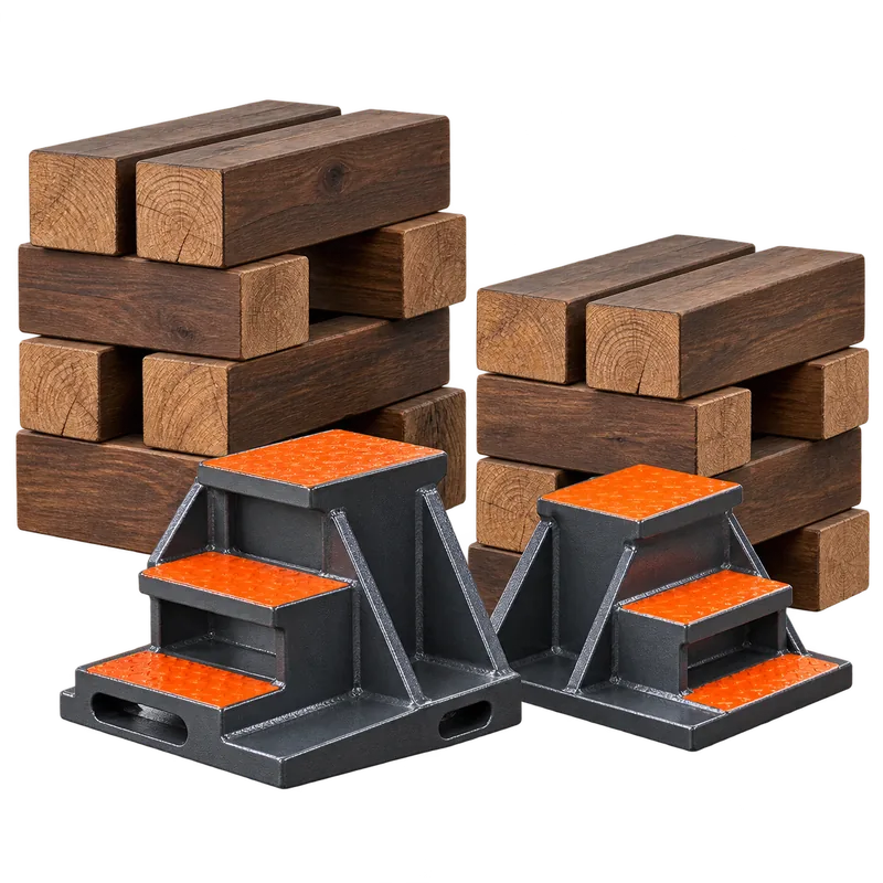
Blocking and cribbing
Provide a stable planned support system as lift height changes. Material, footprint, stacking method and load path must be approved for the work.
Review support equipment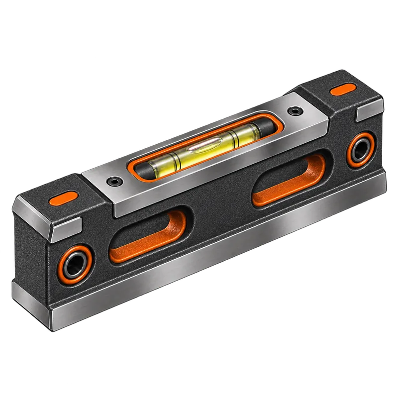
Precision levels
Check approved machine or baseplate surfaces with clean contact, instrument reversal and temperature awareness.
Explore precision levels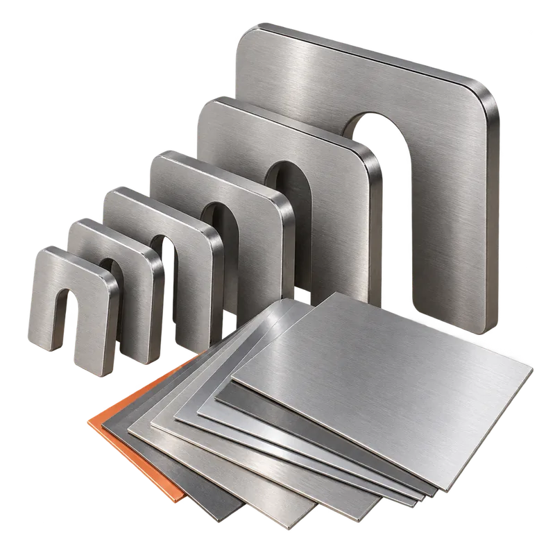
Machinery shims
Use clean, flat, correctly sized material under approved contact areas. Keep stacks practical and protect them during grout and washdown work.
Explore shims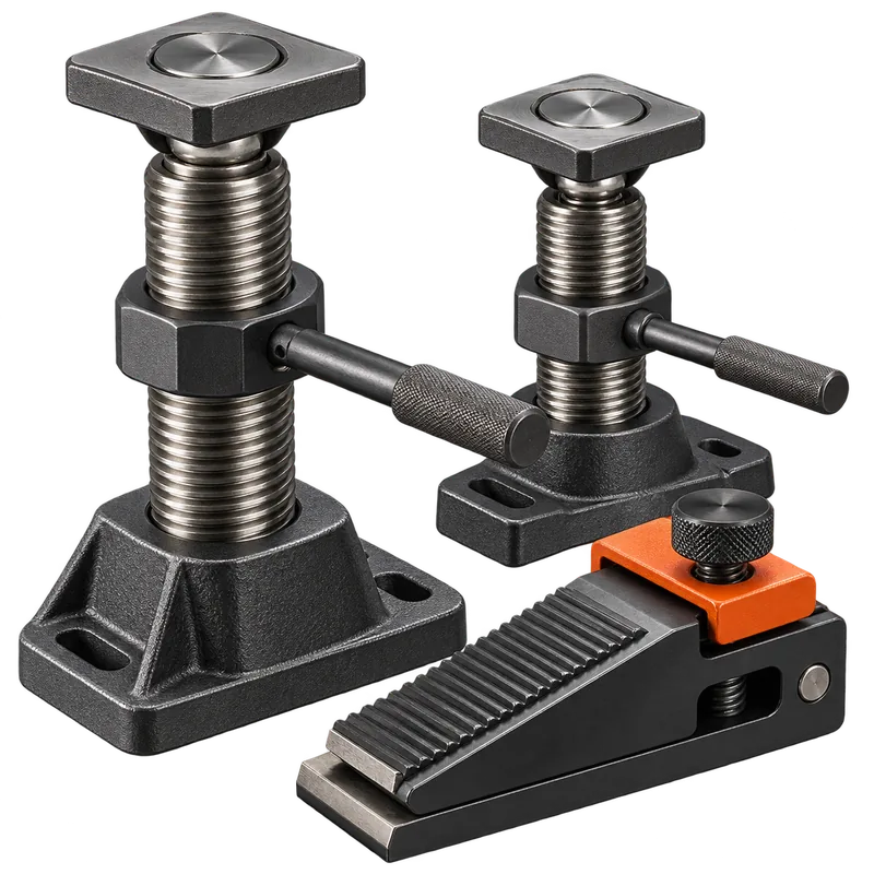
Jack and leveling screws
Apply measured corrections through suitable reaction points, then transfer the load to the permanent support arrangement required by the design.
Explore adjustment tools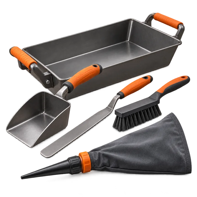
Grout placement tools
Support the specified mixing, placement and finishing method without adding uncontrolled water or improvised practices.
Explore grout toolsLift, support, then move
Control jacking, blocking and roller placement
Hydraulic pressure or jack capacity does not prove the entire setup is stable. The load path includes the machine structure, lift point, jack toe or saddle, jack base, floor, cribbing and every temporary support.
Prepare support
Use a level, firm base with adequate area. Stage approved blocking so no one reaches under an unsupported load.
Lift incrementally
Raise slowly, monitor tilt and support the load as height changes. Keep hands, feet and body outside the collapse and pinch zones.
Set the mover system
Distribute capacity, secure the load to the chosen roller configuration and verify floor condition, steering and stopping before travel.
Enerpac guidance calls for fully supporting each jack or ram at its base and placing blocking or cribbing under a raised load. Hilman recommends selecting machinery-mover configurations for the actual support geometry and floor condition. The approved job plan remains controlling.
Create a stable starting condition
Set position, elevation and baseplate support
| Check | Practical focus | Do not accept |
|---|---|---|
| Reference and orientation | Centerlines, match marks, shaft direction, nozzle orientation and maintenance clearances | A machine rotated, mirrored or shifted to make another mismatch disappear |
| Elevation and level | Specified datum, approved measurement surface, level reversal and repeatable readings | Readings taken over dirt, burrs, paint buildup or an unstable temporary support |
| Anchor bolts | Position, projection, thread condition, sleeves/pockets, washers and nut engagement | Forced bolts, bent anchors or baseplate contact that prevents required adjustment |
| Shims and supports | Correct location, size, contact, cleanliness and practical stack condition | Loose scraps, excessive stacks, edge loading or shims that bridge debris |
| Soft foot / distortion | Machine response as feet are tightened under the approved check method | Using bolt force to pull a foot down without identifying the underlying condition |
| Interfaces | Coupling relationship, pipe/conduit freedom and auxiliary alignment | External systems pulling the machine away from its established condition |
Release a prepared installation
Verify grout readiness before mixing begins
Grout type, surface preparation, clearances, formwork, conditioning, mixing, placement, venting, cure and final tightening must follow the project specification and the exact grout manufacturer's current instructions.
Before release
- Required alignment and hold-point readings accepted
- Baseplate and foundation surfaces prepared as specified
- Forms sealed, braced and arranged for the planned pour path
Materials and environment
- Correct product, lot, quantity and shelf life confirmed
- Water, aggregate and conditioning match the product instructions
- Temperature and weather controls are ready
Placement plan
- Mixing capacity supports continuous placement
- Access, head pressure and vents prevent trapped air
- Crew roles and backup equipment are assigned
After placement
- Protect the grout through the specified cure
- Do not transfer load or torque anchors before release
- Inspect voids, cracks, leaks and final support condition
Close the installation loop
Final alignment, connection and turnover
- Verify permanent supportConfirm grout or chocks are released, temporary devices are removed or transferred as designed, and anchor fasteners are completed in the required sequence.
- Repeat machine checksRecheck level, soft foot, shaft alignment and bolt response after support and connection conditions change.
- Control external strainVerify piping, conduit, guards and auxiliaries connect without moving the machine outside the approved condition.
- Restore machine readinessComplete lubrication, preservation removal, coupling/guard status, rotation checks and housekeeping under the approved commissioning procedure.
- Document the resultRecord as-left readings, shims, fastener status, grout details, inspection results, photos, punch items and required follow-up.
Primary references
Safety and manufacturer guidance
This guide does not replace engineered installation drawings, equipment manuals, grout instructions, a lift/move plan or employer procedures.
Millwright tool questions
Frequently asked questions
Practical answers for comparing tools, planning the work and choosing equipment for the actual assignment.
What should be checked before setting industrial machinery?
Confirm foundation and baseplate readiness, access, load and center-of-gravity information, lifting and moving plans, anchor arrangement, utilities, cleanliness, elevations, references and the prepared landing area. Resolve discrepancies before the machine is suspended or moved into a restricted position.
How level should a machinery baseplate be before grouting?
Use the tolerance and reference points specified by the equipment manufacturer, engineering documents and installation procedure. Establish stable support, measure with suitable verified tools and document readings; a generic level value should not replace the project requirement.
When is a baseplate ready for grout?
Grout readiness normally requires verified elevation and level, stable support, correct anchors and clearances, completed formwork and sealing, clean prepared surfaces, planned vents and placement paths, and approval under the project procedure. Do not grout while alignment or support questions remain unresolved.
Should anchor bolts be fully tightened before alignment?
Follow the approved installation sequence. Anchor condition and tightening affect baseplate and machine geometry, so rough alignment, grouting, cure, final tightening and final alignment must occur in the specified order with documented torque or tension requirements.
Continue into the directory
Build the installation tool system
Use the Machinery Installation Tools directory for toe jacks, hydraulic sets, rollers, shims, levels, jack screws and grout-placement equipment.