
Inspect. Measure. Move. Verify.
Machinery alignment tools
A practical guide to the laser systems, dial setups, shims, inspection tools and positioning equipment used to turn alignment readings into controlled machinery corrections.
Field guide: https://millwrightsupply.com/machinery-alignment-tools-guide.html
The tool is not the whole method
Reliable alignment connects machine condition, measurement and movement
An alignment instrument can calculate a correction, but it cannot repair a loose foundation, identify every source of strain or guarantee the machine moved as intended. Good alignment work establishes the equipment condition first, creates a repeatable measuring setup and controls each correction until the final readings meet the approved requirement.
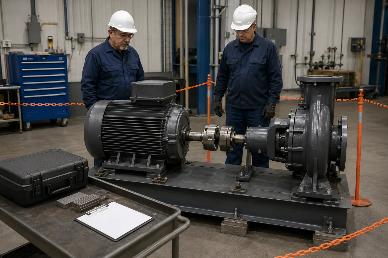
Find the unstable foot before shaft correction
Inspect the condition
Confirm the foundation, hold-downs, coupling condition, shaft runout, soft foot, pipe strain concerns and movement limits required by the job plan.
Measure the relationship
Use a laser or dial method with rigid mounting, correct dimensions, sufficient rotation and repeatable readings referenced to the designated machine.
Correct and verify
Translate the result into controlled vertical and horizontal moves, tighten using the approved sequence, then measure again and document the final condition.
Do not chase numbers around the machine. When readings change unexpectedly, stop and check the base, brackets, backlash, bolt condition, soft foot, strain and measurement repeatability before making another move.
From inspection to correction
Thirteen core alignment-tool groups
The right kit depends on machine configuration, access, required tolerance and the approved method. These groups form the practical system used to establish condition, measure shaft relationship and position equipment.
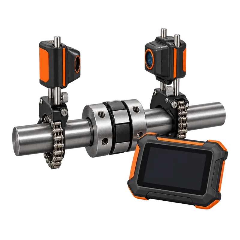
Laser shaft alignment systems
Measure the relationship between rotating centerlines and calculate correction values. Sensor mounting, entered dimensions, rotation and target data must all be correct.
Explore laser systems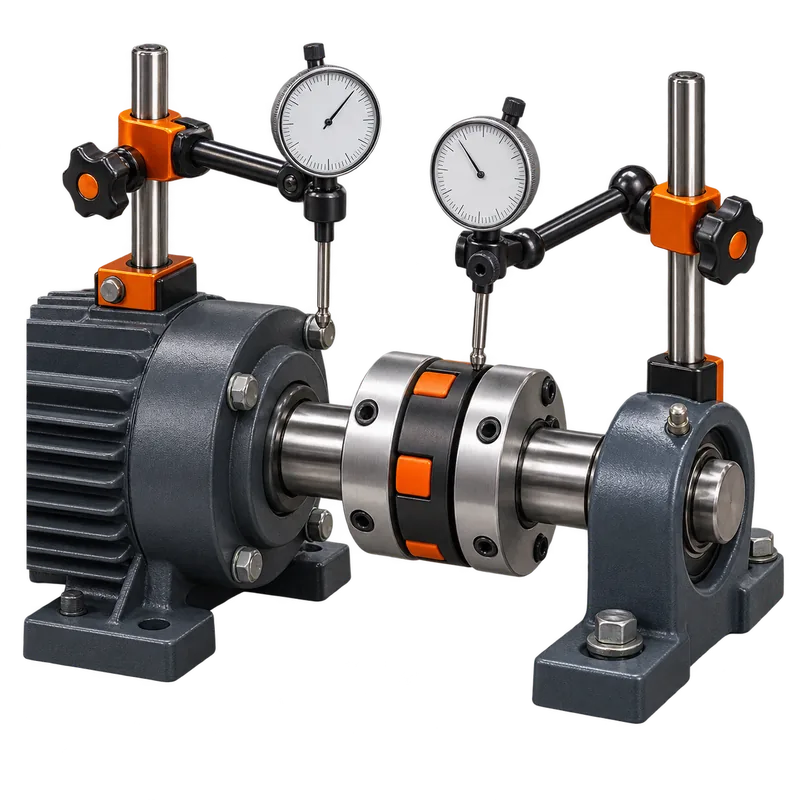
Dial indicator alignment setups
Use indicators, bars, brackets and calculation methods to measure relative shaft position. Setup sag, backlash and reading conventions must be controlled.
Explore dial alignment kits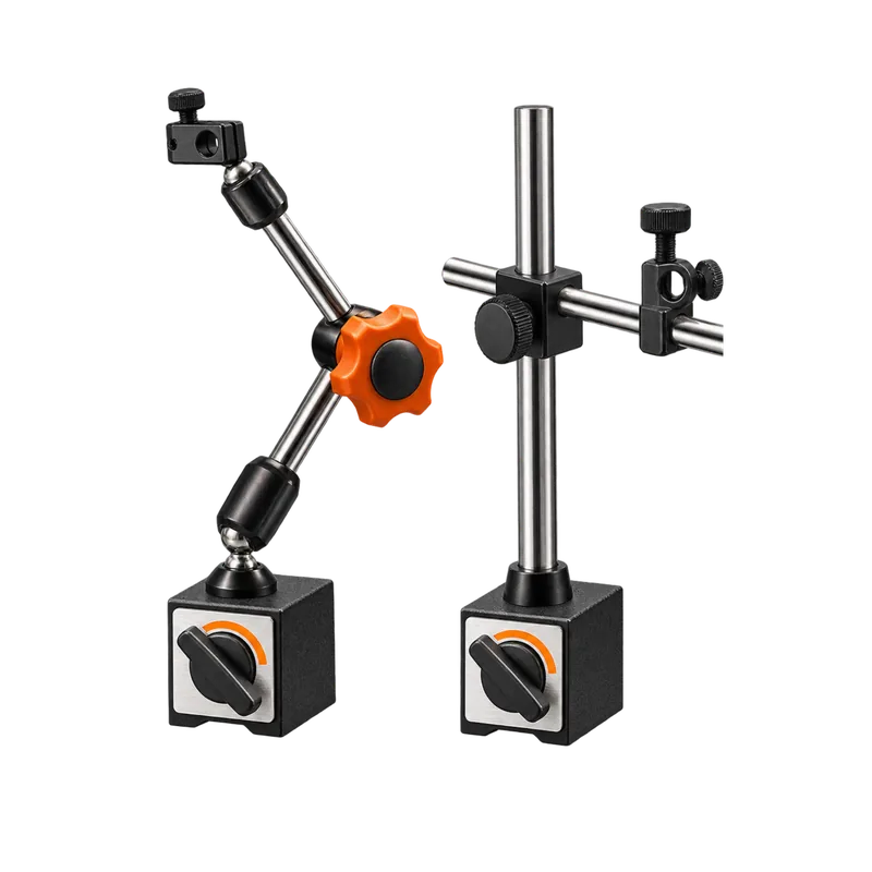
Magnetic bases and brackets
Support indicators from a suitable reference. Clean contact surfaces, short rigid arms and locked joints help prevent base movement from appearing as machine movement.
Explore indicator supports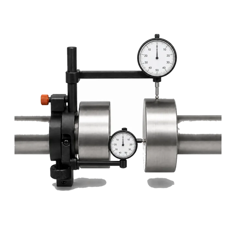
Rim-and-face equipment
Measures coupling rim and face movement with one shaft serving as the reference. Equipment geometry, axial movement and bracket sag affect interpretation.
Review dial alignment equipment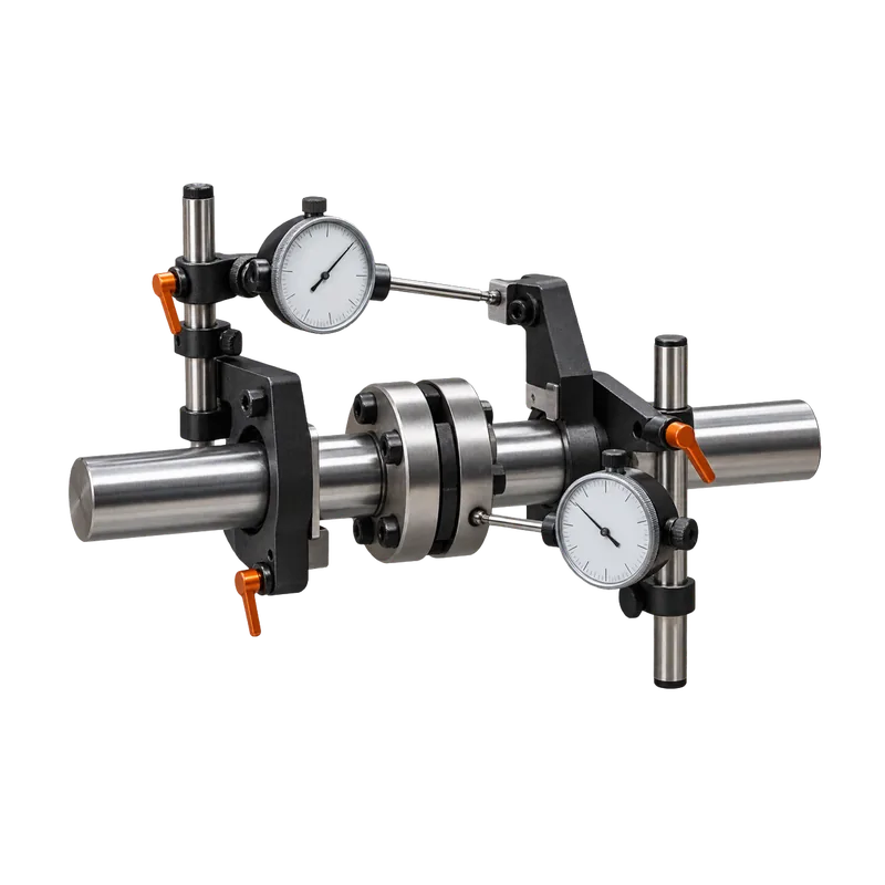
Reverse-dial equipment
Uses indicators reading opposite shafts to calculate offset and angular condition. Bar sag, indicator orientation and accurate machine dimensions remain critical.
Review reverse-dial tools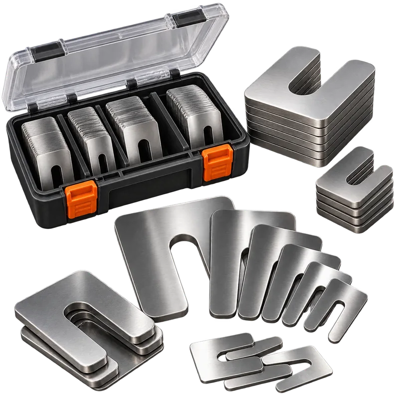
Stainless machinery shims
Provide controlled changes in foot elevation. Use clean, flat, correctly sized shims and keep the stack practical under the approved procedure.
Explore machinery shims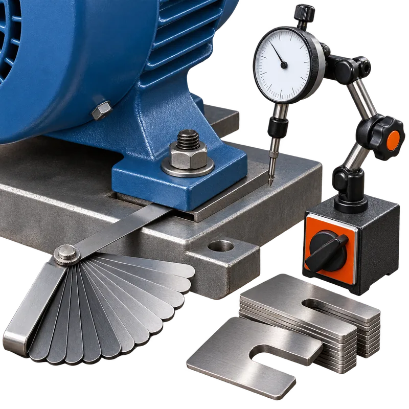
Soft-foot inspection tools
Indicators, feeler gauges, shims and controlled bolt checks help locate feet that lift, rock or distort the frame during tightening.
Review soft-foot tools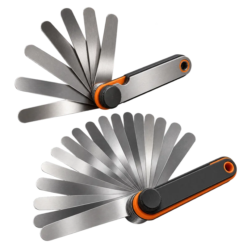
Feeler gauges
Check narrow separations, foot gaps and coupling clearances with known blade thicknesses. Clean blades and a consistent light drag improve reliability.
Explore feeler gauges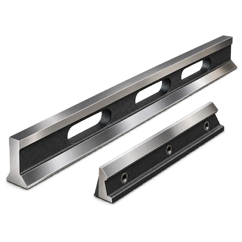
Precision straightedges
Support preliminary coupling alignment and reference checks. They help bring equipment into measuring range but do not replace the required precision method.
Explore straightedges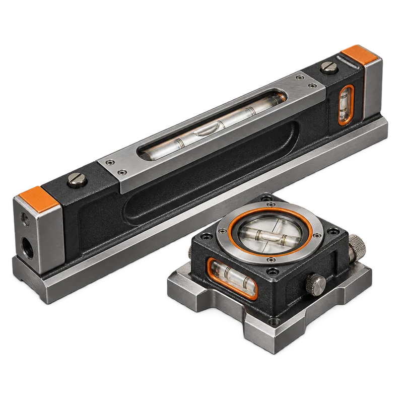
Machinist levels
Check baseplates, soleplates and machine surfaces for small elevation changes. Sensitivity, reversal and temperature control must suit the work.
Explore machinist levels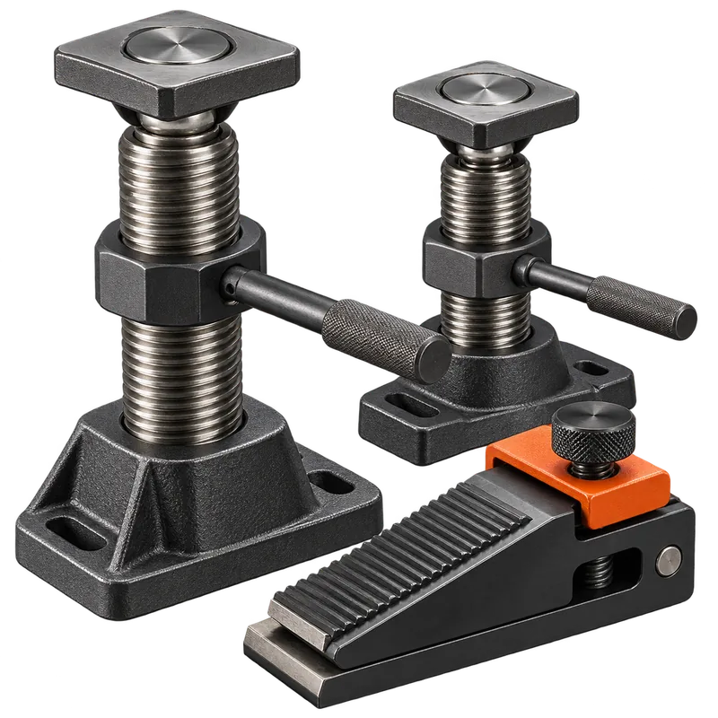
Jacking screws and positioning tools
Apply controlled horizontal movement while the alignment system tracks the change. Secure reaction points and coordinated adjustments reduce overshoot.
Review positioning guidance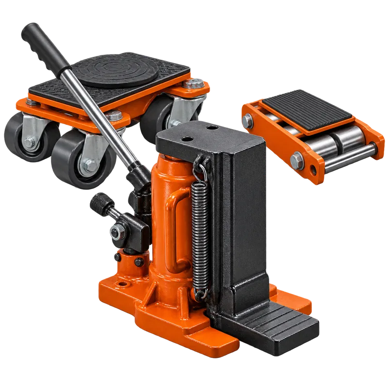
Machinery movers and toe jacks
Support installation-stage lifting and positioning before fine alignment. Capacity, lift points, cribbing and movement controls must follow the lift plan.
Review machinery positioning tools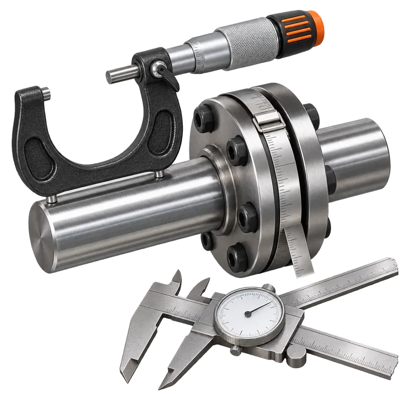
Shaft and coupling measuring tools
Tapes, rules, calipers and micrometers establish dimensions, coupling condition and setup geometry used by the selected alignment method.
Read the measuring-tools guideMatch the method to the machine
Choose an alignment method the setup can support
Access, shaft rotation, coupling geometry, span, movement limits and site requirements determine which method belongs. The approved procedure and available competent personnel remain controlling.
| Method or check | Primary tools | What must be controlled |
|---|---|---|
| Rough coupling alignment | Straightedge, taper or feeler gauge, rule and basic positioning tools | Establish a safe starting condition within the range of the precision system; do not treat rough alignment as final verification. |
| Laser shaft alignment | Paired sensors, brackets, display or software and dimension tools | Correct machine designation, mounting, entered dimensions, measurement mode, rotation and any approved target values. |
| Reverse dial | Two indicators, rigid brackets or bars and calculation worksheet | Indicator orientation, bar sag, backlash, reading signs, shaft rotation and accurate distances between measuring planes and feet. |
| Rim and face | Rim indicator, face indicator, rigid mounting and calculation method | Axial shaft movement, face-reading diameter, bracket sag, coupling condition and consistent reading positions. |
| Soft-foot inspection | Indicator or laser system, feeler gauges, shims and controlled bolting tools | One foot at a time, repeatable bolt condition, external strain and the approved limit and correction method. |
| Machine leveling | Machinist level, reference surfaces, shims or leveling screws | Clean surfaces, instrument reversal, temperature, specified reference and the relationship between level and operating alignment. |
| Runout and coupling condition | Dial indicator, stable base, dimensional tools and approved rotation method | Contact geometry, bearing condition, surface finish, shaft restraint and separation of component runout from alignment readings. |
A disciplined sequence
Typical machinery-alignment workflow
The exact sequence varies by machine and procedure, but the work should move from known condition to repeatable measurement, controlled correction and final verification.
Measure
Inspect the machine condition and prove the measuring setup repeats.
Correct
Make controlled vertical and horizontal moves within the approved method.
Verify
Tighten, rotate or repeat as required, then document the final condition.
- Review the job basisConfirm the machine designation, stationary and movable equipment, required tolerance, target condition, coupling state, documentation and approved procedure.
- Establish a safe conditionApply lockout and stored-energy controls, protect against unintended rotation or movement and verify access before installing tools.
- Inspect the machine trainCheck foundations, bases, hold-downs, coupling fit, shaft or hub condition, runout concerns, lubrication requirements and obvious external strain.
- Correct soft foot and base problemsFind and resolve foot conditions, damaged shims, dirt, burrs, loose fasteners or unsuitable supports before chasing shaft readings.
- Bring the machine into rangeUse the approved rough-alignment and positioning method so brackets and sensors can be installed safely and the precision system remains within range.
- Install and prove the measuring setupMount the system rigidly, enter required dimensions, check sag or sensor stability and repeat readings before accepting the result.
- Make controlled correctionsAdjust vertical position with suitable shims and horizontal position with approved jacking or positioning tools while monitoring the machine response.
- Tighten, remeasure and documentApply the approved tightening sequence, verify the final condition, rotate and repeat as required, then record the result and machine state.
Turn the reading into the move
Control the correction instead of chasing it
Alignment results describe a required change at specific machine locations. The physical move must be planned around bolt clearance, shim condition, jack-screw geometry, base friction and the way the frame responds during tightening.
Vertical moves
- Use clean, flat shims sized for the machine foot
- Confirm existing stacks and remove damaged material
- Recheck soft foot after meaningful shim changes
Horizontal moves
- Use secure jack screws or approved positioning tools
- Work opposing points deliberately to prevent binding
- Watch the live reading where the system permits it
Bolt response
- Follow the specified tightening sequence and torque method
- Watch for movement as each foot is secured
- Investigate a reading that shifts instead of averaging it away
Machine strain
- Separate alignment correction from pipe or conduit strain
- Do not pull connected systems into place with machine bolts
- Verify the required connected and disconnected conditions
Target conditions
- Use only approved thermal-growth or operating targets
- Confirm sign, units and reference convention
- Document whether the final result is cold, hot or compensated
Move limits
- Confirm shim, bolt-hole, coupling and base-clearance limits
- Stop when the required move exceeds the available adjustment
- Escalate base or design problems instead of forcing the machine
Close the loop
Final verification and tool care
The alignment is not complete when the machine reaches the calculated move. It is complete when the secured equipment produces repeatable final readings under the required condition and the result is documented.
Repeat the final sweep
Remeasure after final tightening. Confirm the setup returns to its starting position and that repeated results agree within the method and procedure requirements.
Confirm machine condition
Verify bolts, shims, coupling state, guards, connected systems and any soft-foot or strain checks required before release or turnover.
Record the full result
Document method, units, dimensions, initial and final readings, corrections, targets, machine state and any unresolved condition requiring follow-up.
Inspect brackets and contacts
Clean indicator points, chains, posts, rods and magnetic bases. Check for bent components, loose joints, worn threads and damaged mounting surfaces.
Protect sensors and indicators
Release indicator preload, switch magnetic bases off before storage and return delicate components to fitted cases away from loose tools and moisture.
Maintain verification status
Follow employer requirements for calibration, functional checks, batteries, software or firmware controls and removal of suspect equipment from service.
Millwright tool questions
Frequently asked questions
Practical answers for comparing tools, planning the work and choosing equipment for the actual assignment.
What tools are needed for shaft alignment?
A shaft-alignment setup may include a laser system or dial indicators and rigid brackets, plus measuring tools for soft foot, suitable shims, cleaning tools, torque tools and controlled positioning equipment. The selected method and machine geometry determine the exact kit.
Is laser shaft alignment more accurate than dial alignment?
Either method can produce acceptable results when the equipment, setup, procedure and technician are capable of the required tolerance. Laser systems can reduce calculation and documentation effort, while dial methods require careful control of bracket sag, indicator travel, reading signs and geometry.
Why must soft foot be corrected before final shaft alignment?
Soft foot can distort the machine frame and change shaft position as hold-down bolts are tightened. Check and correct it under the approved procedure so alignment readings represent a stable machine rather than a condition created by uneven support.
How is thermal growth handled during alignment?
Use approved cold-alignment targets based on engineering data, manufacturer information or verified operating history. Do not invent an offset; record the target, machine condition and final readings so the operating-position intent is clear.
Continue into the directory
Build the complete alignment setup
Use the Alignment Tools directory for detailed tool guidance, field notes and exact-product comparison sections.